Programming microcontrollers
A microcontroller, often shortened to MCU, is a full-fledged computer because it consists of a processor (which can also be multicore nowadays), a memory system, and some peripherals. Unlike a standard computer, a microcontroller fits entirely on an integrated chip, is incredibly low-power, and is inexpensive.
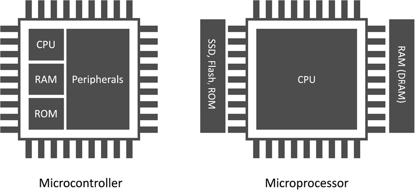
We often confuse microcontrollers with microprocessors, but they refer to different devices. In contrast to a microcontroller, a microprocessor integrates only the processor on a chip, requiring external connections to a memory system and other components to form a fully operating computer.
The following figure summarizes the main differences between a microprocessor and a microcontroller:

As for all processing units, the target application influences their architectural design choice.
For example, a microprocessor tackles scenarios where the tasks are usually as follows:
- Dynamic, which means they can change with user interactions or time
- General-purpose
- Compute-intensive
A microcontroller addresses completely different scenarios, as the applications can:
- Be single-purpose and repetitive
- Have time frame constraints
- Be battery-powered
- Need to fit in a small physical space
- Be cost-effective
Tasks are generally single-purpose and repetitive. Therefore, the microcontroller does not require strict re-programmability. Typically, microcontroller applications are less computationally intensive than microprocessor ones and do not have frequent interactions with the user. However, they can interact with the environment or other devices. As an example, consider the thermostat.
The device only requires monitoring the temperature regularly and communicating with the heating system.
Sometimes, tasks must be executed within a specific time frame. This requirement is characteristic of real-time applications (RTAs), where the violation of the time constraint may affect the quality of service (soft real time) or be hazardous (hard real time). A car’s anti-lock braking system (ABS) is an example of a hard RTA because the electronic system must respond within a time frame to prevent the wheels from locking when applying brake pedal pressure.
RTA applications require a latency-predictable device, so all hardware components (CPU, memory, interrupt handler, and so on) must respond in a precise number of clock cycles.
Hardware vendors commonly report latency in the datasheet, expressed in clock cycles.
The time constraint poses some architectural design adaptations and limitations for a general-purpose microprocessor. For instance, the memory management unit (MMU), used to translate virtual memory addresses, is generally not integrated into CPUs for microcontrollers.
Microcontroller applications can be battery-powered, as the device has been designed to be low-power. As per the time frame constraints, power consumption also poses some architectural design differences from a microprocessor. Without going deeper into the hardware details, all the off-chip components generally reduce power efficiency as a rule of thumb. That is the main reason microcontrollers typically integrate memories within a chip.
Microcontrollers typically have lower clock frequency than microprocessors to consume less energy.
Microcontrollers are also an ideal choice for building products that need a compact physical footprint and cost-effectiveness. Since these devices are computers within a chip, the package size is typically a few square millimeters and is economically more advantageous than microprocessors.
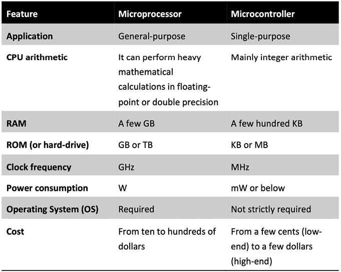
In the following table, we have summarized what we have just discussed for easy future reference:

Figure 1.16: Table comparing a microprocessor with a microcontroller
In the next section, we will go deeper into microcontrollers’ architectural aspects by analyzing the memory architecture and internal peripherals crucial for ML model deployment.
Memory architecture
Microcontrollers are CPU-based embedded systems, meaning the CPU is responsible for interacting with all its subcomponents.
All CPUs require at least one memory to read the instructions and store/read variables during the program’s execution. In the microcontroller context, we typically dedicate two separate memories for the instructions and data: program and data memory.
Program memory is non-volatile read-only memory (ROM) reserved for the program to execute. Although its primary goal is to contain the program, it can also store constant data. Thus, program memory is similar to our everyday computers’ hard drives.
Data memory is volatile memory reserved to store/read temporary data. Therefore, it operates similarly to RAM in a personal computer, as its contents are lost when switching off the system.
Given the different program and data memory requirements, we usually employ other semiconductor technologies. In particular, we can find flash technologies for the program memory and static random-access memory (SRAM) for the data memory.
Flash memories are non-volatile and offer low power consumption but are generally slower than SRAM. However, given the cost advantage over SRAM, we can find larger program memory than data memory.
Now that you know the difference between program and data memory, where would you store the weights for a deep neural network model?
The answer to this question depends on whether the model has constant weights. If the weights are constant during inference, it is more efficient to store them in program memory for the following reasons:
- Program memory has more capacity than SRAM.
- It reduces memory pressure on the SRAM, since other functions require storing variables or chunks of memory at runtime.
We want to remind you that microcontrollers have limited memory resources, so a decision like this can significantly reduce SRAM memory usage.
Microcontrollers offer extra on-chip features to expand their capabilities and make these tiny computers different from each other. These features are the peripherals, which are discussed in the upcoming subsection.
Peripherals
Peripherals are essential in microcontrollers to interface with sensors or other external components.
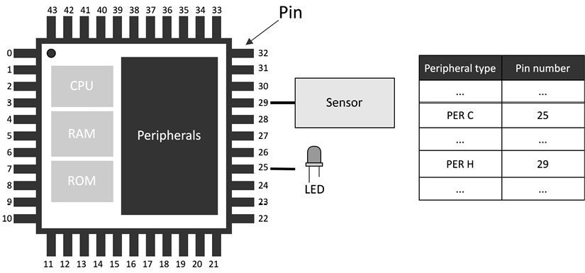
Each peripheral has a dedicated functionality and is assigned to a metal leg (pin) of the integrated circuit.
You can refer to the peripheral pin assignment section in the microcontroller datasheet to find out each pin’s functionalities.
Hardware vendors typically number the pins anti-clockwise, starting from the top-left corner of the chip, marked with a dot for easy reference, as shown in Figure 1.17:

Figure 1.17: Viewed from the top, pins are numbered anti-clockwise, starting from the top-left corner, marked with a dot
Peripherals can be of various types, and the following subsection will provide a brief overview of those commonly integrated into microcontrollers.
General-purpose input/output (GPIO or IO)
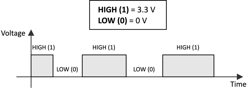
GPIOs do not have a predefined and fixed purpose. Their primary function is to provide or read binary signals that, by nature, can only live in two states: HIGH (1) or LOW (0). The following figure shows an example of a binary signal:

Typical GPIO usages are as follows:
- Turning on and off an LED
- Detecting whether a button is pressed
- Implementing complex digital interfaces/protocols such as VGA
GPIO peripherals are versatile and generally available in all microcontrollers. We will use this peripheral often, such as turning on and off LEDs or detecting whether a button has been pressed.
Analog/digital converters
When developing tinyML applications, we will likely deal with time-varying physical quantities, such as images, audio, and temperature.
Whatever these quantities are, the sensor transforms them into a continuous electrical signal interpretable by the microcontrollers. This electrical signal, which can be either a voltage or current, is called an analog signal.
The microcontroller, in turn, needs to convert the analog signal into a digital format so that the CPU can process the data.
Analog/digital converters act as translators between analog and digital worlds. Thus, we have the analog-to-digital converter (ADC) that converts the electrical signal into a digital format, and the digital-to-analog converter (DAC), which performs the opposite functionality.
In this book, we will use this peripheral to transform the analog signal the microphone generates into a digital format.
Serial communication
Communication peripherals integrate standard communication protocols to control external components. Typical serial communication peripherals available in microcontrollers are I2C, SPI, UART (commonly called serial), and USB.
The serial peripheral will be used extensively in our projects to transmit messages from the microcontroller to our computer (we’ll refer to this communication as over the serial throughout this book). For example, we will use this peripheral to debug our applications and generate media files.
Timers
In contrast to all the peripherals we just described, timers do not interface with external components, since they are used to trigger or synchronize events. For example, a timer can be set up to acquire data from a sensor at a specific time interval.
Having covered the topic of peripherals, we have completed our overview of the tinyML ingredients. With a grasp of the relevant terminology and fundamental concepts about ML, power/energy consumption, and microcontrollers, we can now introduce the development platforms used in this book.


