Search icon CANCEL
Subscription
0
Cart icon
Your Cart (0 item)
Close icon
You have no products in your basket yet
Save more on your purchases! discount-offer-chevron-icon
Savings automatically calculated. No voucher code required.
Arrow left icon
Explore Products
Best Sellers
New Releases
Books
Videos
Audiobooks
Learning Hub
Free Learning
Arrow right icon
Arrow up icon
GO TO TOP
ESP8266 Robotics Projects

You're reading from   ESP8266 Robotics Projects DIY Wi-Fi controlled robots

Arrow left icon
Product type Paperback
Published in Nov 2017
Publisher Packt
ISBN-13 9781788474610
Length 210 pages
Edition 1st Edition
Tools
Concepts
Arrow right icon
Author (1):
Arrow left icon
Pradeeka Seneviratne Pradeeka Seneviratne
Author Profile Icon Pradeeka Seneviratne
Pradeeka Seneviratne
Arrow right icon
View More author details
Toc

Table of Contents (9) Chapters Close

Preface 1. Getting Ready FREE CHAPTER 2. Building a Mini Round Robot with Original ESP8266 3. Using Encoders 4. Building a Mini Round Robot with the Feather HUZZAH ESP8266 5. Line-Following Zumo Robot 6. Building an ESP8266 Robot Controller 7. Building a Gripper Robot 8. Photo Rover Robot

Building the Robot Controller


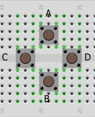
Let's get started with building the Robot Controller that can be used to control the Romi Robot over the Wi-Fi network. The controller has four movement related push buttons that can be used to control the movement of the robot (Figure 6.24). The following is a list of operations associated with each movement-related push button:

  • A: FORWARD
  • B: BACKWARD
  • C: LEFT
  • D: RIGHT

Figure 6.24: The Robot Controller movement-related push buttons

Figure 6.25 shows the wiring diagram that can be used to build the Robot Controller with the Adafruit Feather HUZZAH ESP8266 and the four movement-related push buttons. You can use any GPIO pin (#0, #2, #4, #5, #12, #13, #14, #15, or #16) at the top edge of the Feather PCB to connect to the push buttons. The wiring diagram uses GPIO #12, #13, #14, and #15 as the input. Connect the push buttons with GPIO pins, as follows:

  • Push button A (FORWARD): GPIO #12
  • Push button B (BACKWARD): GPIO #13
  • Push button C (LEFT): GPIO #14
  • Push button D (RIGHT...
lock icon The rest of the chapter is locked
Register for a free Packt account to unlock a world of extra content!
A free Packt account unlocks extra newsletters, articles, discounted offers, and much more. Start advancing your knowledge today.
Unlock this book and the full library FREE for 7 days
Get unlimited access to 7000+ expert-authored eBooks and videos courses covering every tech area you can think of
Renews at $19.99/month. Cancel anytime
Banner background image