Exploring materials
Earlier, we set for ourselves the goal of changing the color of the cylinder when it is hit by a projectile. To do so, we will need to change the actor's material. A material is an asset that can be added to an actor's mesh (which defines the physical shape of the actor) to create its look. You can think of a material as paint applied on top of an actor's mesh or shape. Since an actor's material determines its color, one method of changing the color of an actor is to replace its material with a material of a different color. To do this, we will first be creating a material of our own. It will make an actor appear red.
Creating materials
We can start by creating a new folder inside the FirstPersonBP directory and calling it Materials. Navigate to the newly created folder and right-click inside empty space in the content browser, which will generate a new asset creation popup. From here, select Material to create a new material asset. You will be prompted to give the new material a name, which I have chosen to call TargetRed.
Material properties and Blueprint nodes
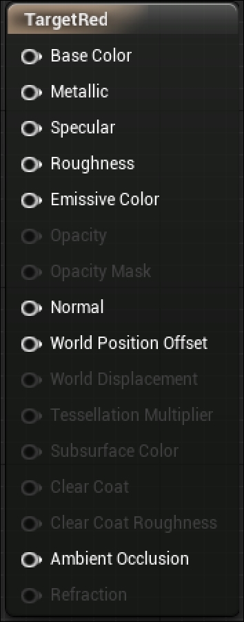
Double-click on TargetRed to open a new editor tab for editing the material, like this:

You are now looking at Material Editor, which shares many features and conventions with Blueprints. The center of this screen is called the grid, and this is where we will place all the objects that will define the logic of our Blueprints. The initial object you see in the center of the grid screen, labeled with the name of the material, is called a node. This node, as seen in the previous screenshot, has a series of input pins that other material nodes can attach to in order to define its properties.
To give the material a color, we will need to create a node that will give information about the color to the input labeled Base Color on this node. To do so, right-click on empty space near the node. A popup will appear, with a search box and a long list of expandable options. This shows all the available Blueprint node options that we can add to this Material Blueprint. The search box is context sensitive, so if you start typing the first few letters of a valid node name, you will see the list below shrink to include only those nodes that include those letters in the name. The node we are looking for is called VectorParameter, so we start typing this name in the search box and click on the VectorParameter result to add that node to our grid:

A vector parameter in the Material Editor allows us to define a color, which we can then attach to the Base Color input on the tall material definition node. We first need to give the node a color selection. Double-click on the black square in the middle of the node to open Color Picker. We want to give our target a bright red color when it is hit, so either drag the center point in the color wheel to the red section of the wheel, or fill in the RGB or Hex values manually. When you have selected the shade of red you want to use, click on OK. You will notice that the black box in your vector parameter node has now turned red.
Tip
Downloading the example code
You can download the example code files from your account at http://www.packtpub.com for all the Packt Publishing books you have purchased. If you purchased this book elsewhere, you can visit http://www.packtpub.com/support and register to have the files e-mailed directly to you.
To help ourselves remember what parameter or property of the material our vector parameter will be defining, we should name it color. You can do this by ensuring that you have the vector parameter node selected (indicated by a thin yellow highlight around the node), and then navigating to the Details panel in the editor. Enter a value for Parameter Name, and the node label will change automatically:

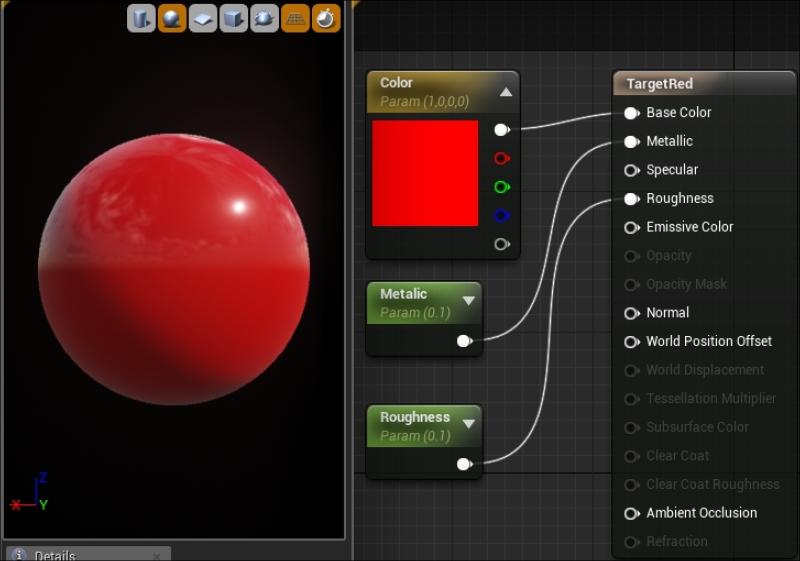
The final step is to link our color vector parameter node to the base material node. With Blueprints, you can connect two nodes by clicking and dragging one output pin to another node's input pin. Input pins are located on the left-hand side of a node, while output pins are always located to the right. The thin line that connects two nodes that have been connected in this way is called a wire. For our material, we need to click and drag a wire from the top output pin of the color node to the Base Color input pin of the material node, as shown in the following screenshot:

Adding substance to our material
We can optionally add some polish to our material by taking advantage of some of the other input pins on the material definition node. 3D objects look unrealistic with flat, single color materials applied, but we can add additional reflectiveness and depth by setting a value for the materials Metallic and Roughness inputs. To do so, right click in empty grid space and type scalar into the search box. The node we are looking for is called ScalarParameter.

Once you have a scalar parameter node, select it, and go to the Details panel. A scalar parameter takes a single float value (a number with decimal values). Set Default Value to 0.1, as we want any additive effects to our material to be subtle. We should also change Parameter Name to Metallic. Finally, we click and drag the output pin from our Metallic node to the Metallic input pin of the material definition node.
We want to make an additional connection to the Roughness parameter, so right-click on the Metallic node we just created and select Duplicate. This will generate a copy of that node, without the wire connection. Select this duplicate Metallic node and then change the Parameter Name field in the Details panel to Roughness. We will keep the same default value of 0.1 for this node. Now click and drag the output pin from the Roughness node to the Roughness input pin of the Material definition node.
The final result of our Material Blueprint should look like what is shown in the following screenshot:

We have now made a shiny red material. It will ensure that our targets will stand out when they are hit. Click on the Save button in the top-left corner of the editor to save the asset, and click again on the tab labeled FirstPersonExampleMap to return to your level.


