Understanding the main parameters
It is now time to talk about the parameters involved in our turning operations. First of all, what is a parameter? In short, a parameter is a value or a setting that we can change.
Of course, some parameters are easier to change than others. For example, changing the axial movement speed for our tool is very simple, while on the other hand, changing the maximum cutting power may require a bigger and more powerful lathe.
Also, as we will shortly discover, some values are somehow connected to others; changing one parameter may change one or more others, so we have to optimize parameters according to our lathe specs and to the part we want to machine.
Let’s find out what the main parameters are that we have to work with.
Turning speed
The turning speed is a measure of how fast the chuck is spinning; it may be measured in radians per time unit ( ) or in revolutions per time unit (
 ).
).
As shown in the screenshot, the bent vector represents the part spinning along the longitudinal axis:
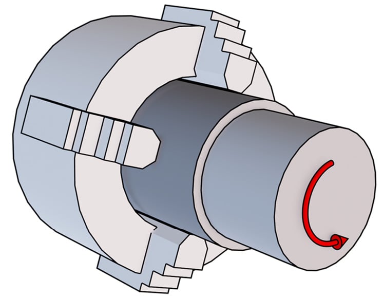
Figure 1.5: Turning-speed visualization
One revolution of our chuck corresponds to an angle ( ) of 360° or
  (depending on whether it’s measured in degrees or radians). But, since
  is measured in revolution per time unit, we need to divide the angle by the same time unit, so that from the angle, we get angular speed (
 ).
).
In short, we just need to remember this formula:

Old lathes had turning speeds that were only adjustable by manually changing the belt and pulleys, or changing the gears. Today, there are lathes that can control the rotation speed with inverters and encoders. So, depending on your lathe, the turning speed may or may not be a parameter that's easy to change.
Note
Please be careful when dealing with time units: sometimes the time unit may be seconds and sometimes minutes. As you can imagine, one revolution per minute is very different from one revolution per second, so when using any formula, please always be sure of its units!
Cutting speed
The cutting speed ( ) is the relative speed between our cutting tool and the surface it is cutting. There is only one important thing to notice, which is that the cutting speed is highly dependent on the radial position of our tool: the bigger the diameter means the higher the cutting speed (at a constant rotation speed).
As you can see in the screenshot, we have a common rotation speed for the two tools (since the chuck rotation is always the same); however, as you may have noticed from the different arrow lengths, the tool that is machining a bigger diameter has a much higher cutting speed (vertical vector) than the tool machining a smaller diameter:
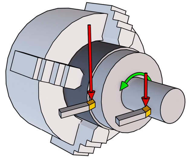
Figure 1.6: Cutting-speed visualization
Note
A vector can be defined by a magnitude and a direction. Magnitude is represented by the arrow length, while the direction is represented by the direction of the pointed tip.
Cutting speed is typically measured in meters per minute (m/min), and there is a very simple formula for calculating it:

Here,  is the diameter in millimeters (mm) and
  is revolutions per minute (RPM).
For example, let’s imagine we have a chuck rotating at 500 RPM, and we are performing a longitudinal operation at a constant radial distance of 50 mm (basically, we are machining a stock with a diameter of 100 mm). What is the cutting speed seen by our tool? It's very simple:

Now that we have seen the cutting-speed formula, it should be now clear that when machining a shape with different radial coordinates assumed by our tool, the cutting speed will be subject to changes. Since the working diameter is not a parameter we can change (it is related to the part shape we want to machine), in order to change the cutting speed, we can only adjust the chuck RPM. That’s why most of the time, you will see bigger parts spinning slower and smaller parts spinning faster! Once the tool is almost at the rotation axis, the cutting speed will always drop to zero, independently of how fast the chuck is rotating.
Cutting depth
The cutting depth ( ) is a parameter that gives us a measure of how much we impose an interpenetration between our tool and our part; it is measured in mm. Basically, it is related to how much of our cutting edge is engaged with the stock:
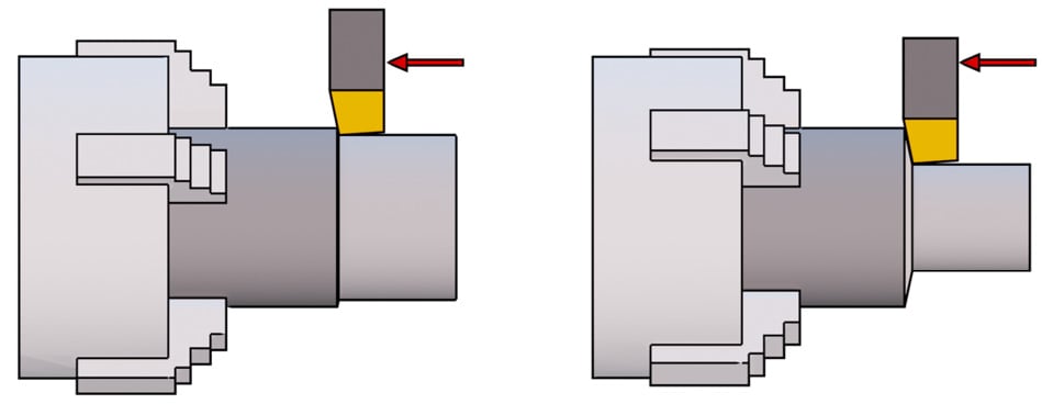
Figure 1.7: Cutting-depth visualization
As we can see, there are two tools machining the same diameter. The one on the left, however, is engaging the stock at a very small cutting depth, and therefore it removes only a thin layer of material. The tool on the right is cutting at a much bigger cutting depth and therefore it is removing a much thicker layer, and most of the cutting edge is engaged.
Please note that cutting depth is not always measured in the radial direction; sometimes, it can be measured in the axial direction. It mainly depends on the type of machining process we use (we will explain this in the Exploring main machining strategies section later in the chapter).
Higher cutting depth means more material removed and therefore faster machining, but requires more cutting power and leads to higher stress on our tool and our part. For this reason, please consider that higher cutting depths may partially bend our stock (especially if it is long and supported on one side only). Bending may lead to weird shapes with a rough finish.
Cutting feed
The cutting feed ( ) is a parameter that measures how much our tool is advancing along the cutting direction at every revolution of our chuck, and therefore it is measured in mm per revolution (mm/rev)
Similar to cutting depth, higher feeds lead to higher machining speed at the cost of higher tool wear and higher power being required. The part finish is highly connected with feed values; as a rule of thumb, a lower feed value means higher surface quality.
In the following screenshot, we have two tools machining the same stock at the same cutting depth:
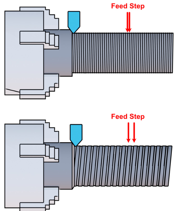
Figure 1.8: Feed visualization
However, in the first example, there is a much smaller feed step than in the second, so though they have the same turning speed, the tool on the bottom will reach the end of the stock much quicker, at the cost of higher surface roughness.
Be careful, as certain operations must be performed at a constant feed, such as threading. Threads have a constant pitch per rotation; therefore, we must set the feed to be equal to the thread pitch in such a scenario.
Note
Threading is the process of making a thread. It may be related to a male thread (such as a screw) or a female thread (such as a nut).
Adjusting the feed will also affect the chip. We can assume that a lower feed will produce a very long and entangled chip, while a higher feed will produce small particles. This is illustrated in the following screenshot:
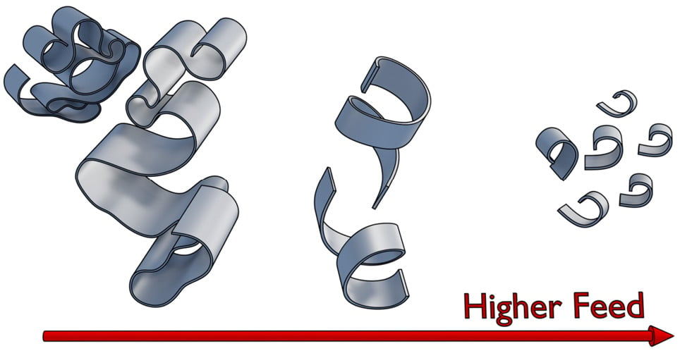
Figure 1.9: Chip formation related to feed
We should always try to hit a sweet spot in chip thickness, width, and length. The ideal chip shape is the one in the middle of the screenshot.
Note
Chip formation is a very interesting world of its own. I don’t really want to distract you from the main topic; however, if you want to learn more about chip formation and different chip types, I suggest you take a look at this interesting link: https://www.bdeinc.com/blog/types-of-chips-formed-during-cnc-milling/.
Cutting power
The cutting power is the mechanical power required to machine our part at a given set of parameters. It is measured in kilowatts (kW).
Before setting all our parameters, we must always check whether our lathe is powerful enough to handle the machining we want to perform. This is the simple formula to remember:

Here,  is the cutting power measured in kW;
  is the cutting speed measured in m/min;
  is the cutting depth measured in mm;
  is the feed step measured in mm/rev; and, finally,
  is the specific cutting force measured in MegaPascal (MPa).
As you may have noticed, there is a new value called  that we haven’t seen yet.
  is a parameter related to material strength, tool shape, feed ratio, and cutting depth. This is a difficult parameter to evaluate, and I don’t want to bother you with complex calculations… but luckily, I don’t have to. We can simply refer to tables where equations are already sorted out by experts. Please note that this is a rough approximation of the real value, so you may want to take it with a grain of salt and have a bit of a safety margin on cutting power!
Here, we can find an example of the most common iron alloys:
|
Material/Feed |
0.1 mm/rev |
0.2 mm/rev |
0.3 mm/rev |
0.4 mm/rev |
0.6 mm/rev |
|
Cast iron |
3200 MPa |
2800 MPa |
2600 MPa |
2500 MPa |
2300 MPa |
|
Mild steel |
3600 MPa |
3100 MPa |
2700 MPa |
2500 MPa |
2300 MPa |
|
Medium steel |
3100 MPa |
2700 MPa |
2600 MPa |
2500 MPa |
2300 MPa |
|
Hard steel |
4050 MPa |
3600 MPa |
3300 MPa |
3000 MPa |
2600 MPa |
|
Tool steel |
3200 MPa |
2900 MPa |
2600 MPa |
2500 MPa |
2400 MPa |
Figure 1.10: Kc approximation for steel and iron
Using such a table is quite simple: we simply select the row according to the material we are about to machine, then we select the column with a feed similar to the one we plan to use, and the result approximates the real  value.
Note
If you are intrigued by this parameter, you can find all the formulas for a precise evaluation of  here: http://www.mitsubishicarbide.net/contents/mhg/enuk/html/product/technical_information/information/formula4.html.
As you can see, there is a very useful formula where we can insert our cutting parameters to get our  value. If you are hungry for more formulas, there is a very good explanation about
  here: https://www.machiningdoctor.com/glossary/specific-cutting-force-kc-kc1/#k1c-and-mc-chart-for-material-group.
With that last equation, it is now easy to understand that all parameters are connected and that we must change them accordingly to meet the maximum cutting power available for our lathe.
You may be wondering whether it is a must to target maximum power. No, it is not, but from the production point of view, not using our machine at its full potential will cost us more money per hour. However, a typical scenario where we will not use maximum cutting power is when we are machining a fragile material that we may damage with our chuck closed at maximum force to sustain chuck torque.
Now that we have covered the main parameters, we should better understand our lathe. Next, let’s jump into something juicier: turning operations and strategies!


