Search icon CANCEL
Subscription
0
Cart icon
Your Cart (0 item)
Close icon
You have no products in your basket yet
Save more on your purchases! discount-offer-chevron-icon
Savings automatically calculated. No voucher code required.
Arrow left icon
Explore Products
Best Sellers
New Releases
Books
Videos
Audiobooks
Learning Hub
Free Learning
Arrow right icon
Arrow up icon
GO TO TOP
Visualize Complex Processes with Microsoft Visio

You're reading from   Visualize Complex Processes with Microsoft Visio A guide to visually creating, communicating, and collaborating business processes efficiently

Arrow left icon
Product type Paperback
Published in May 2023
Publisher Packt
ISBN-13 9781837631926
Length 314 pages
Edition 1st Edition
Arrow right icon
Authors (2):
Arrow left icon
Senaj Lelic Senaj Lelic
Author Profile Icon Senaj Lelic
Senaj Lelic
David Parker David Parker
Author Profile Icon David Parker
David Parker
Arrow right icon
View More author details
Toc

Table of Contents (14) Chapters Close

Preface 1. Chapter 1: Choosing the Correct Business Process Diagram Type 2. Chapter 2: Choosing the Best Visio Edition for Our Needs FREE CHAPTER 3. Chapter 3: Learning to Manually Create Process Flow Diagrams 4. Chapter 4: Using Visio for Desktop with BPMN 5. Chapter 5: Utilizing Data Sources to Create and Enrich Business Process Diagrams 6. Chapter 6: Learn How to Diagram Efficiently 7. Chapter 7: Preparing Diagrams for Presentation and Collaboration 8. Chapter 8: Securing and Providing Access to Diagrams 9. Chapter 9: Integrating Visio with Other Microsoft Apps 10. Chapter 10: Customizing Master Shapes and Templates 11. Chapter 11: Improving the Provided Flowchart Shapes 12. Index 13. Other Books You May Enjoy

Automatically highlighting unglued connectors

The Dynamic connector master can be enhanced to be displayed as a red dashed line, for example, if it is not connected at both ends.

Again, we must edit the Dynamic connector master in local Document Stencil and consider the LinePattern and LineColor cells in the Line Format section and the BegTrigger and EndTrigger cells in the Glue Info section, as in the following screenshot:
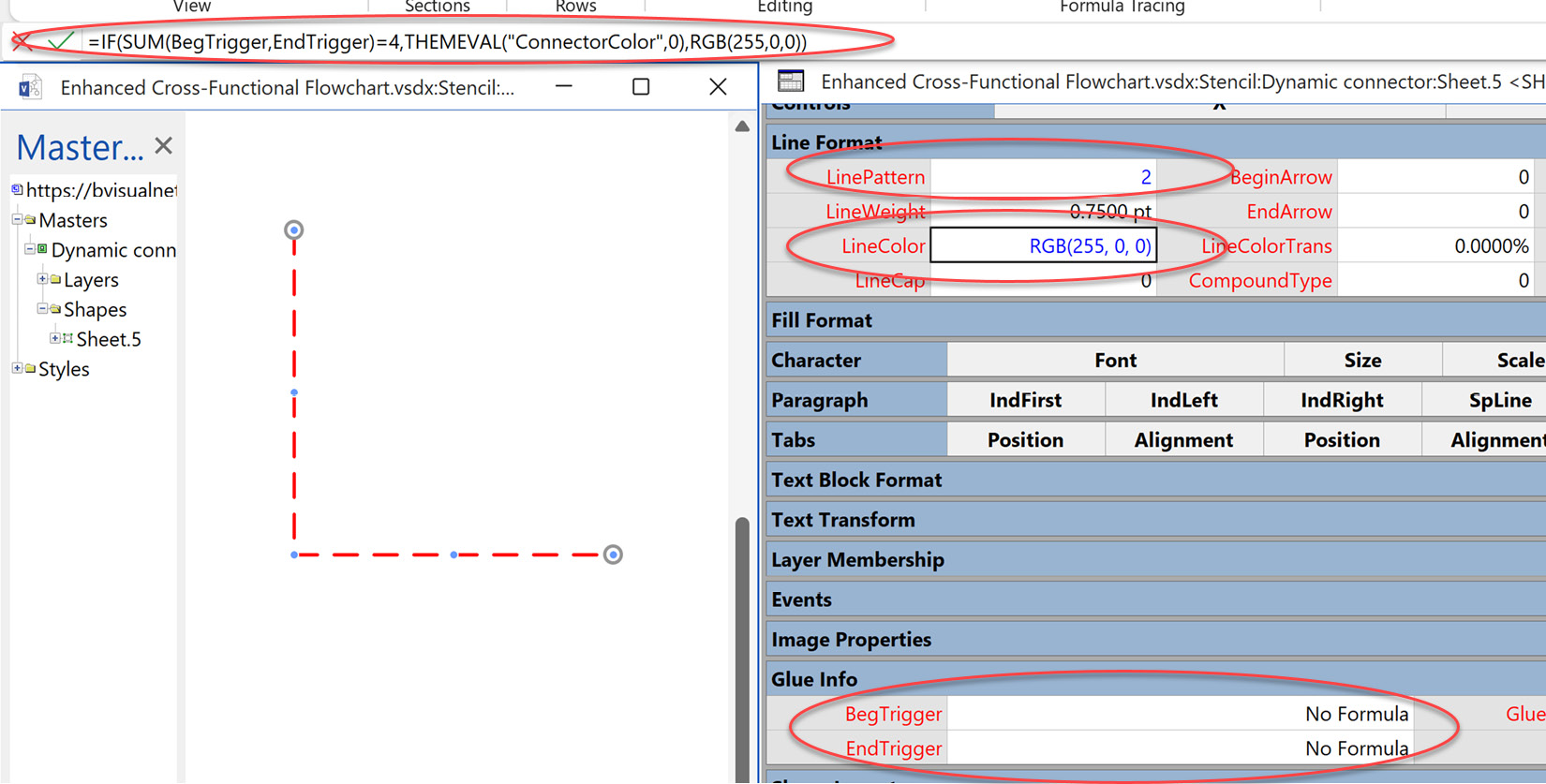
Figure 11.15 – Show unconnected lines with a red dash

Figure 11.15 – Show unconnected lines with a red dash

It is possible to check whether the connector is connected at both ends by checking that the formulas that will be automatically assigned by Visio to the BegTrigger and EndTrigger cells each evaluate to 2.

The default formula for the LinePattern cell is as follows:

=THEMEVAL("ConnectorPattern")

Visio has an ID number for each of the built-in patterns, which you can see on the Format Shape panel. So, if we want it to be dashed, which is ID = 2, we can...

lock icon The rest of the chapter is locked
Register for a free Packt account to unlock a world of extra content!
A free Packt account unlocks extra newsletters, articles, discounted offers, and much more. Start advancing your knowledge today.
Unlock this book and the full library FREE for 7 days
Get unlimited access to 7000+ expert-authored eBooks and videos courses covering every tech area you can think of
Renews at $19.99/month. Cancel anytime
Banner background image