About encoders and odometry
Odometry is measuring how a position has changed over time. We can combine measuring and estimation to determine where you are on a route. An encoder is a sensor designed to measure distance traveled via wheel turns. They are like tachometers, but encoders measure position whereas tachometers measure only speed. Combined with time, they can make a speed measurement too.
Absolute and relative sensing
Sensors for a robot’s location come in two primary forms. They are as follows:
- Absolute sensors encode a position to a repeatable position. They have a limited range or resolution, such as encoding a position along a known line. For example, GPS sensors have exact positioning with low resolution, suitable for meters but not millimeters.
- Relative sensors tend to be cheaper. However, they produce a relative change in position, which needs to be combined with the previous state to get an absolute estimate – this means that errors can accumulate. Relative encoders are one example of relative sensors, also known as incremental encoders.
If a sensor tells you where something is at, it is absolute. It is relative if it tells you how much something has moved by.
Types of encoders
Most encoder designs work by passing markers or code over a sensor that counts or decodes the pulses.
Encoders come in a few forms. Some example types are as follows:
- A potentiometer or variable resistor can sense an absolute encoder position by measuring resistance. Servo motors use them. However, potentiometers are not suitable for continuous rotations such as wheels, as their track lengths limit them. In addition, regular movement wears them down, as they move contacts across each other.
- Mechanical encoders pass electrical contacts over each other, producing on and off pulses. They are subject to heavy wear, so I do not recommend them.
- Optical encoders shine a light through a disk or strip with slots and detect the passing of slots in front of light sensors. They can come in absolute and relative flavors. They can be susceptible to interference from light sources or just dirt.
- Magnetic encoders detect the movements of magnets in a disc using hall-effect sensors. Dirt, light interference, and physical wear do not affect them so much. Hall-effect sensors produce a voltage depending on a magnetic field – encoder modules produce pulses from this.
The motors we chose came with rotary magnetic encoders in a convenient and small format as part of the package. They are incremental encoders.
Encoder pulse data
We can better understand encoders by looking at the pulses they output. Relative encoders usually output digital pulse chains, 1s and 0s. The simplest form is just to count pulse edges by detecting marks passing a sensor, as the following diagram shows:

Figure 6.1 – Simple pulse encoding
On the left of Figure 6.1 is a disk with a rotation arrow. On the disk are four white marks – representing the markers passing a sensor. The black rectangular object is the sensor that detects the markers. The sensor produces a value of 0 when it isn’t detecting a marker and 1 when it is – making a bunch of pulses or a stream of binary bits with values of 1 or 0.
We can count the pulses to get an idea of far the wheel has turned. We count a high pulse as 1 and a low pulse as 0. We can also count edges, the changes from 0 to 1 and 1 to 0. Counting edges gives us eight steps per wheel turn. The graph to the right of the following diagram shows these pulses.
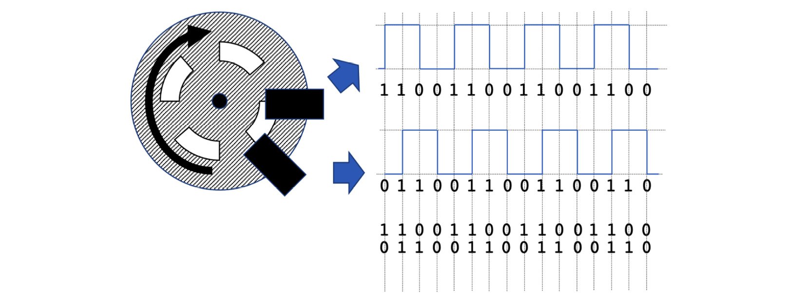
We are likely to want to increase that sensitivity and detect which direction a wheel is going. To do that, we add a second sensor to the same wheel, as the following diagram shows:

Figure 6.2 – Quadrature pulse encoding
Figure 6.2 adds a second sensor to catch the markers at a slightly different time from the first, generating pulses out of phase; this means we have two streams of pulses.
At the top right is the pulse graph for the first sensor, with the digits we had read from times between the pulses added, showing a pulse train of 16 bits for the same period.
The middle graph shows the additional sensor, with the out-of-phase 16-digit pulse train. Below the graphs are the two states combined at each point in time as Gray code, with 2 bits of information on where we are relative to the last position. We have twice as many edges, increasing the sensor resolution and also encoding the wheel’s direction. If we reverse the wheel, this sequence will reverse. This system is known as quadrature encoding.
Let’s look at the encoders on our robot in the next section.


