Routing and rules
When it comes to setting up our virtual lab network, we want to try and mimic real-world segmentation strategies. With that being said, it is hard to talk about OT networking without at least commenting on the Purdue model. This model has been used as a reference by almost all industries as a method of building out a baseline for segmenting levels in the network. The levels are as follows:
- Level 5: Enterprise
- Level 4: Site Business Systems
- Level 3: Operations and Control
- Level 2: Localized Control
- Level 1: Process
- Level 0: I/O
So, true to form, we will take the same approach in our lab. We will start by placing the Virtual PLC into Level 1, the SCADA VM into Level 2, the Windows 7 Engineering Workstation into Level 3, and finally our Kali Linux attack host into Level 5. We will need to log into ESXi and click on Networking. This will bring up a screen showing multiple tabs related to the networking infrastructure of ESXi, as shown here:
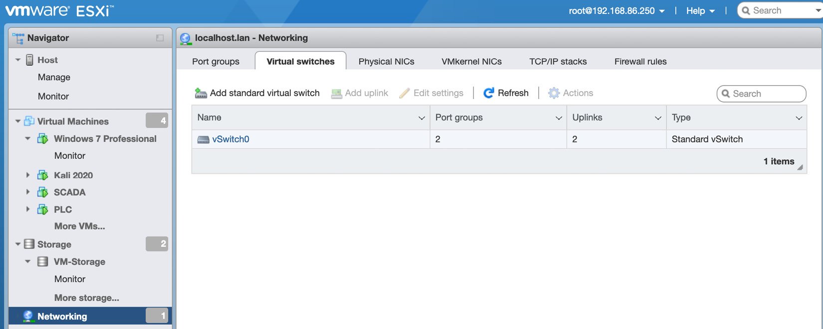
Figure 1.29 – Networking dashboard
We will create a new switch on the Virtual switches tab. Start by filling out the vSwitch Name option and change Link discovery Mode to Both, as shown in the following screenshot. This allows details about the physical and virtual switches to be published and available:
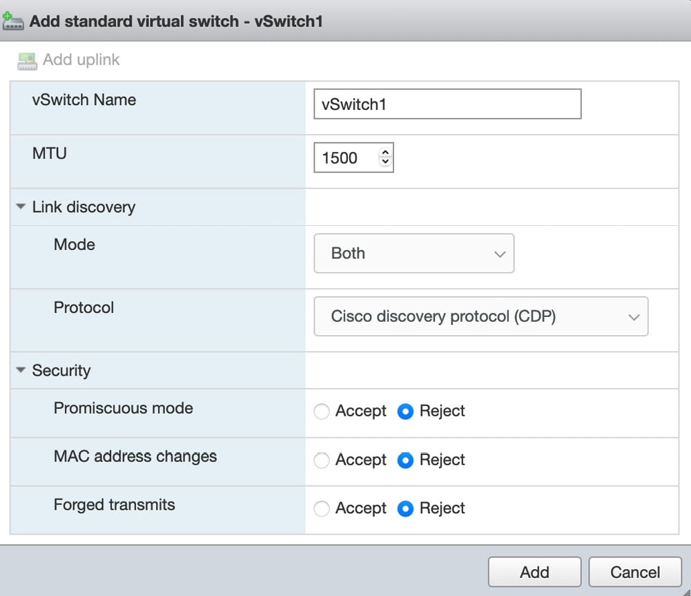
Figure 1.30 – Configuring the virtual switch
We will go back and change Promiscuous mode in Chapter 5, Span Me If You Can, when we discuss Intrusion Detection Systems (IDS). Once completed, you should see your new virtual switch.
Next, we want to move on to the Port groups tab. From here, we want to click Add port group, which will bring up a modal where we can set a Name, VLAN, and associate port group to a Virtual switch. For port security, we are going to default to inheriting the security settings from vSwitch1, which we created in the previous step. All these details can be seen in the following screenshot:
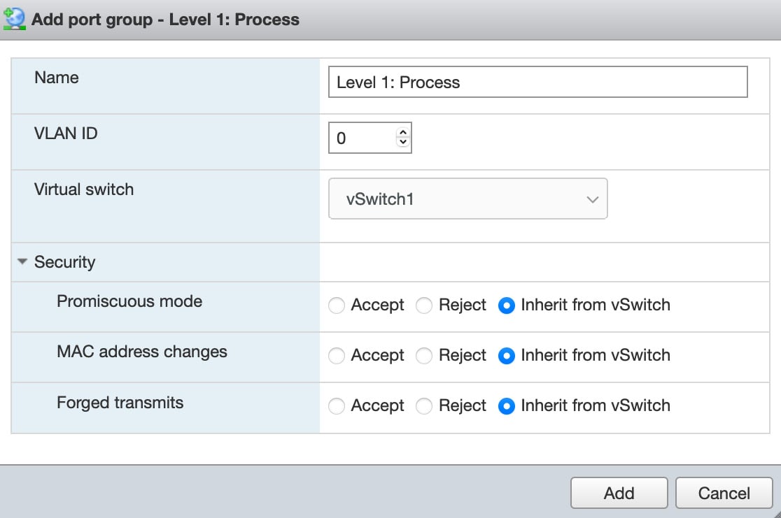
Figure 1.31 – Port group configuration
Now, we want to complete the process by adding the remaining networks:
- Enterprise
- Site Business systems
- Operations & Control
- Localized Control
Once completed, you will see the port groups associated with the dedicated switches. Note that there are many ways to complete segmentation and adhere to the Purdue model:

Figure 1.32 – Port Groups dashboard
As you can see, we still have all our VMs associated with the VM network. The next step will be to move the VMs into their own individual segments and manually set their IP addresses and ranges. We will start with the PLC VM, so we need to select Virtual Machines from the navigator bar and then click on PLC VM. Click the Edit button; this will take you to the following page:
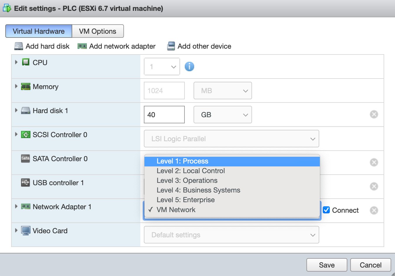
Figure 1.33 – Port Groups selection
We want to switch our Network Adapter from VM Network to Level 1: Process and then click Save. Next, we want to manually set the IP address for the PLC. So, we need to open the console, log into the PLC, and navigate to Network settings.
You will see the following page:
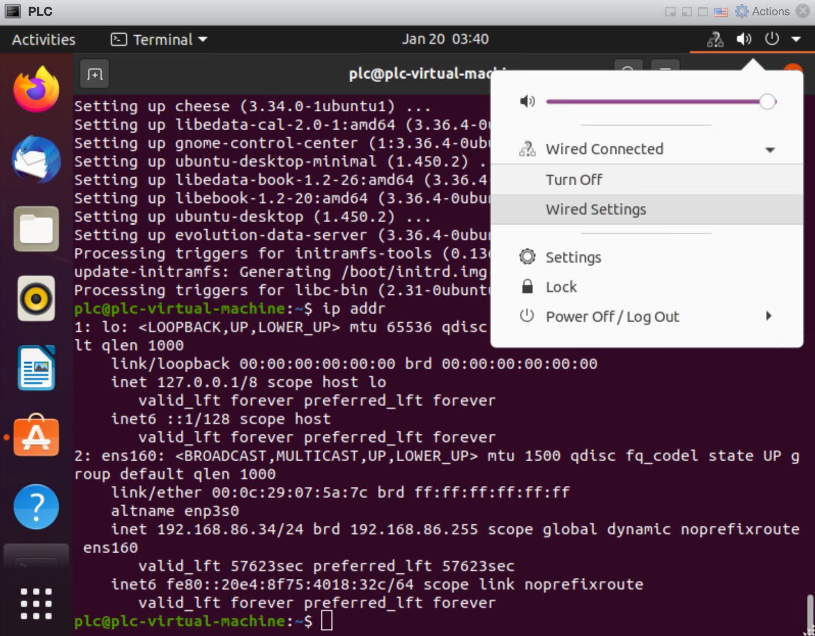
Figure 1.34 – Network settings
From here, we can click the Wired Settings option. Then, a pop-up window will appear. Next, you want to select the gear icon, which is located next to the purple slider, as shown in the following screenshot:

Figure 1.35 – Wired network interface
At this point, we should take a moment to discuss our IP address scheme.
Here, we will break each network segment into a dedicated IP range, as shown in the following table:

Now, we can pre-assign IP addresses to the VMs that we have built out.
We will assign the following IP addresses:
- PLC:
192.168.1.10 - SCADA:
192.168.2.10 - Workstation:
192.168.3.10 - Kali:
172.16.0.10
We can check our machines to make sure that the IP addresses have taken affect by running the ip addr command on the Linux-based distros, similar to what's shown in the following screenshot:
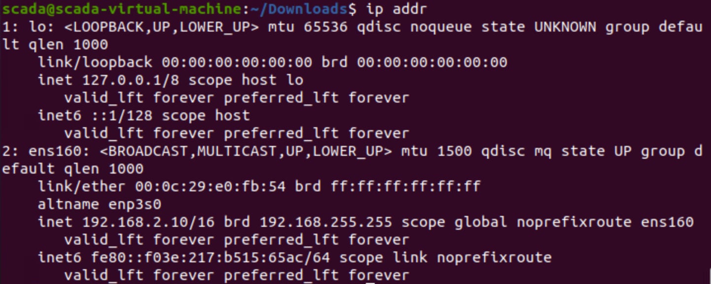
Figure 1.36 – Checking the network address
From here, select IPv4 and then choose the Manual option. The option to set the Linux-based distro IP address for all three – PLC, SCADA, and Kali – should appear underneath Addresses, as shown in the following screenshot:
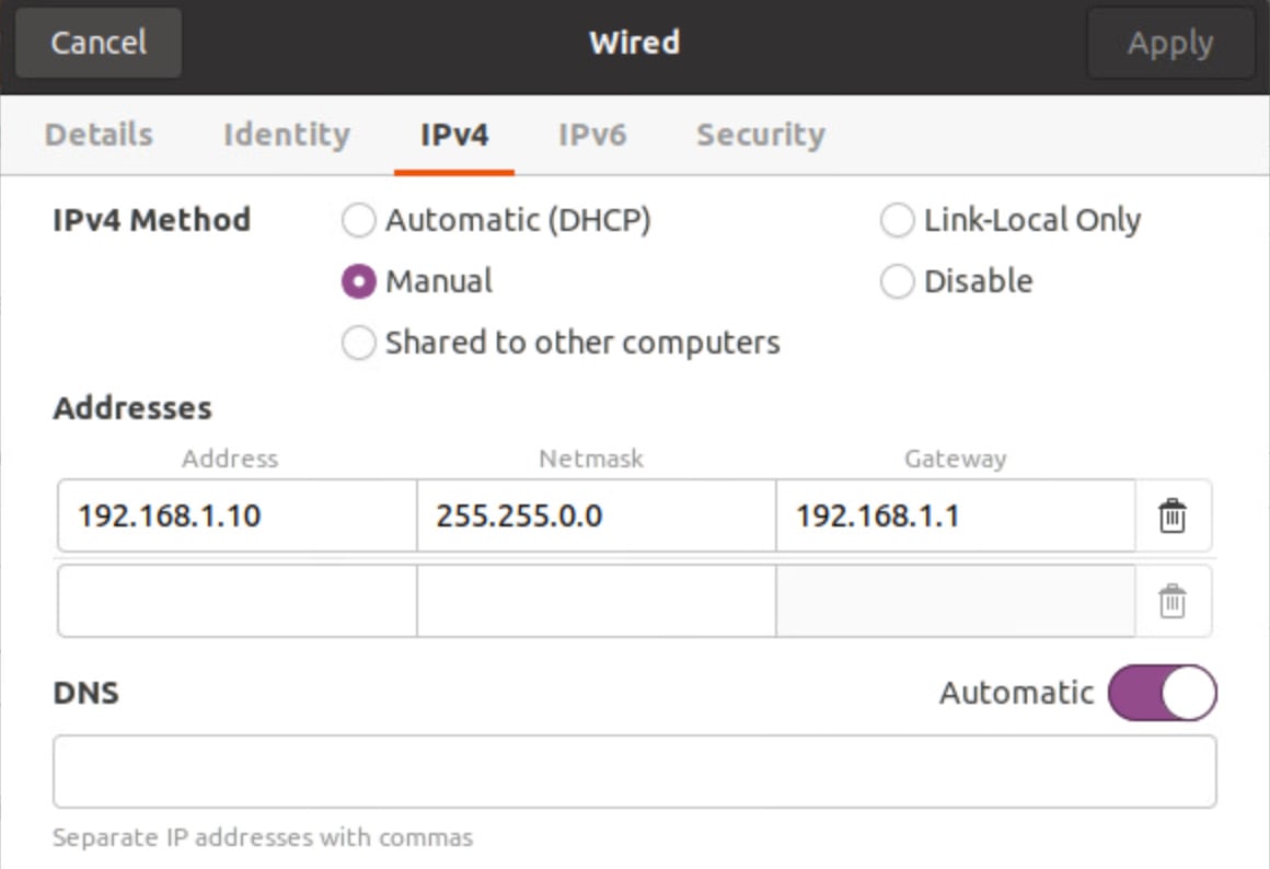
Figure 1.37 – Ubuntu manual IP configuration
Now, we can move on to the Windows 7 configuration and set the IP address manually there as well. The Windows 7 configuration looks like this:
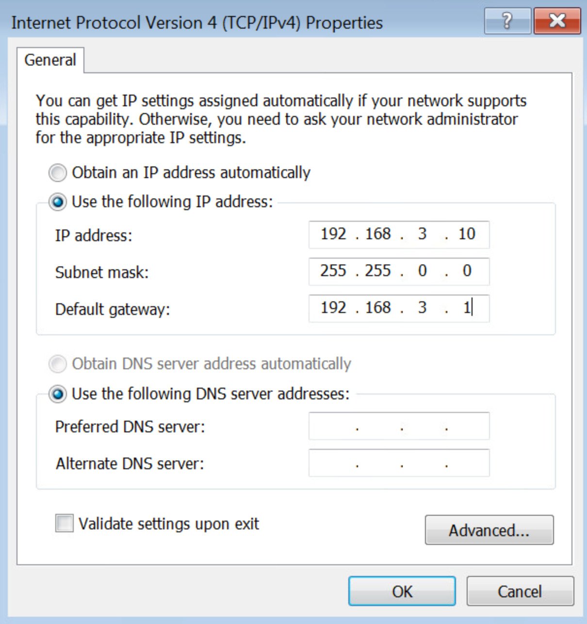
Figure 1.38 – Windows 7 network configuration
Make sure that PLC, SCADA, and Workstation can all ping each other by running the ping command, as shown in the following screenshot:
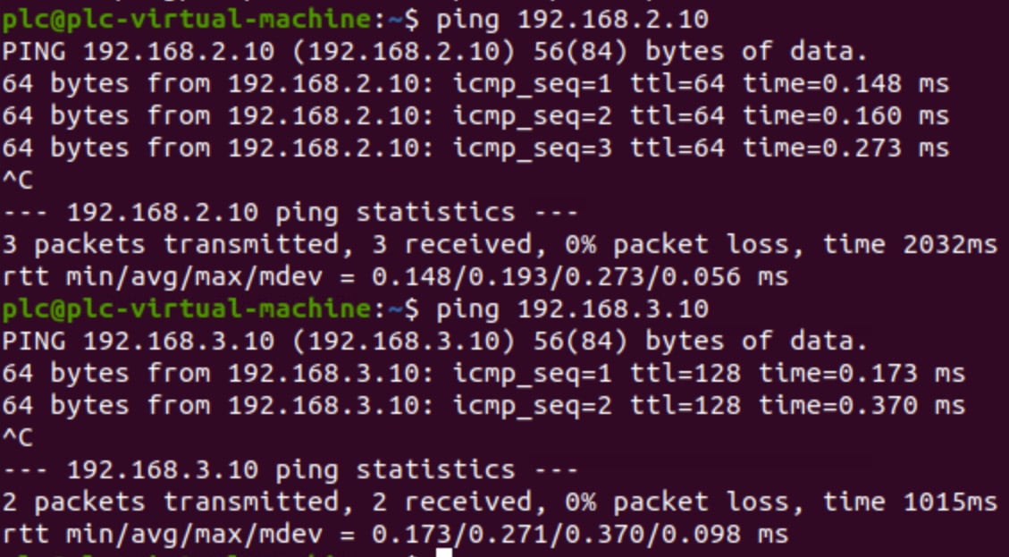
Figure 1.39 – Checking communication between VMs
We have now successfully set up the network segmentation so that it represents that of the Purdue model. The IP addresses have all been statically set, and we've tested the communication between the levels and the VMs.


