Hardware configuration
We will now build the different boards based on the Arduino Uno, which we will later connect to the Galileo board via Wi-Fi.
Let's start the Arduino module with the LED light:
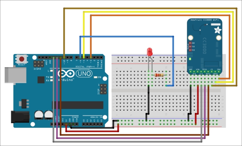
First, we need to connect the IRQ pin of the CC3000 board (that's the rightmost pin when you're facing the board) to pin 3 of the Arduino Uno.
Next, we will connect the VBAT pin to pin 5, and the CS pin to pin 10.
Then, we proceed to connecting the Adafruit SPI pins to the Arduino pins: MOSI, MISO, and CLK pins go to pins 11, 12, and 13, respectively.
Finally, we'll take care of the power supply. Adafruit's Vin should be connected to Arduino's 5V pin, and GND to GND.
The last things that we need to connect are the LED and resistor. Connect the resistor to pin 6 of the Uno.
Then, place the LED in series with the resistor. The negative pin of the LED should connect to the GND node.
You may refer to the following illustration for the entire configuration of the Arduino LED module:

Here is how my module turned...


