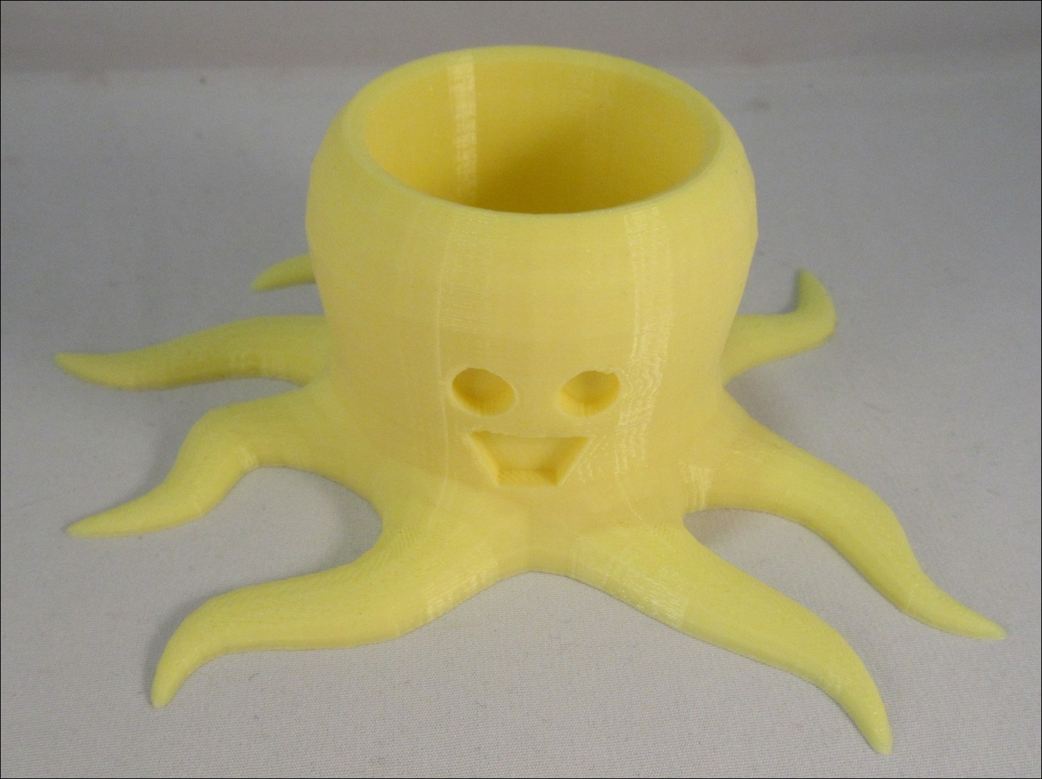
Adding a face
Functionally, the design is complete, but it's the little details that really make it. This little octopus would be much cuter with a face:
- To start making a cute face, make sure the Edit Mode is off (Tab) and make sure the 3D cursor is at the origin (Shift + C). Now, create a circle (Shift + A) by navigating to Mesh | Circle:
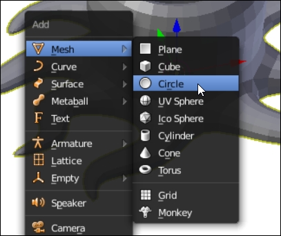
- The circle is hidden inside the octopus, so with the circle still selected, switch to the local view (Numpad /). Since this circle will become the face, it's good to name it
Faceusing the same method to rename the object as the one used earlier.The circle is a flat object that has no face and is just a ring of points and lines. That's easy enough to fix:

- Switch to the Edit Mode (Tab). Now, with all the points or edges selected (A) from the 3D View menu, navigate to Mesh | Faces | Make Edge/Face or press F on the keyboard:
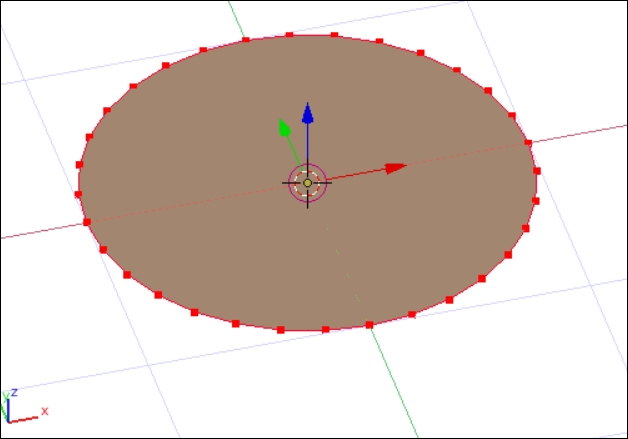
The
Make Edge/Facecommand attempts to make a connected face from the selected vertices or lines. It can be quite intelligent, but if the points are not all flat, the edges may twist unexpectedly. - While still in the Edit Mode, switch to the top view (Numpad 7), and with all the points still selected, move (G) them to the left of the green y axis:
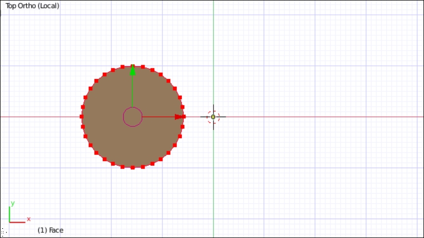
Duplicating an object outside of the Edit Mode creates a new object. However, duplicating points in the Edit Mode doesn't technically create a new object. Whatever is selected is duplicated while remaining a part of the same object. Objects in Blender can have many parts to them, all inside the same object.
- Duplicate (Shift + D) all the points and place the duplicated points on the opposite side of the green y axis line:
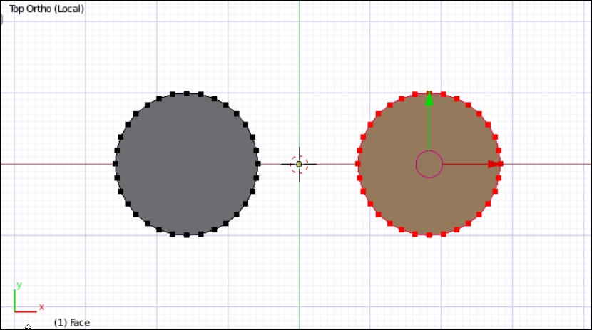
In this way, objects created while in the Edit Mode are just points, lines, and faces added to the existing object, even if they're not connected.
- While still in the Edit Mode (making sure the 3D cursor is still at the origin), add (Shift + A) a plane to the face object by navigating to Mesh | Plane:
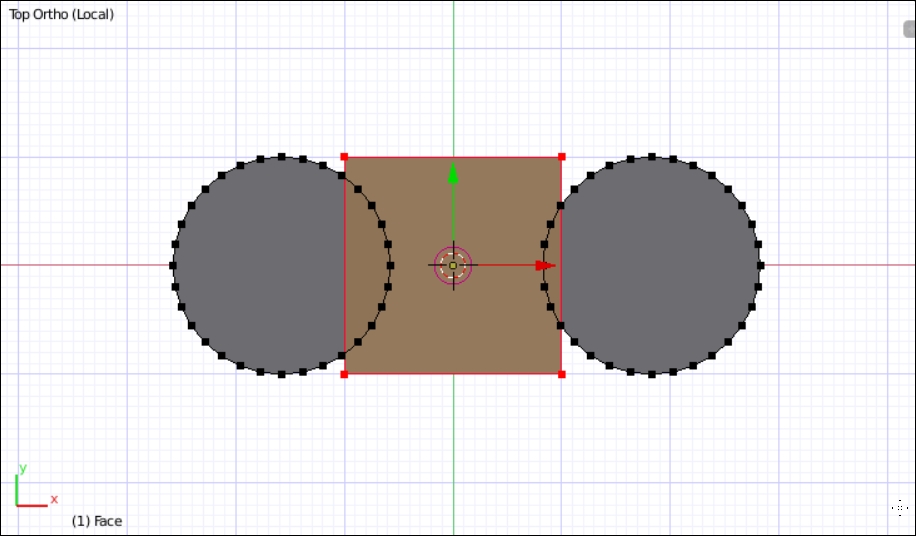
- Move (G) the plane down along the y axis (Y) about 3 units:
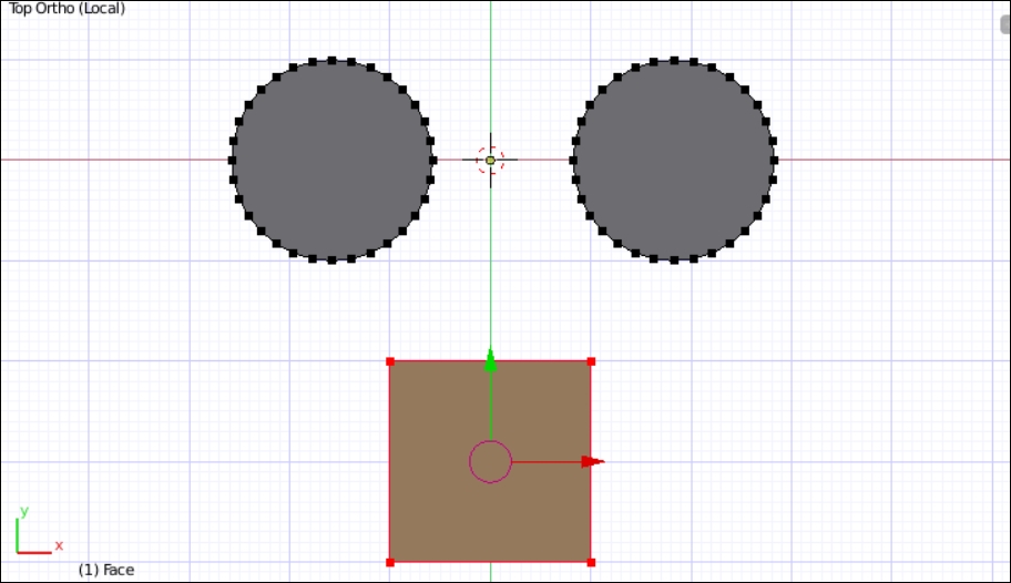
- Deselect all the points (A) and select the two points at the top of the plane. Then, scale (S) them up about twice in order to create a smiling mouth:
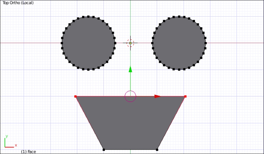
- The shapes now look like a face but only in two dimensions. To give it the additional dimension required, select all the points (A twice) and extrude them (E) about 4 or 5 units.
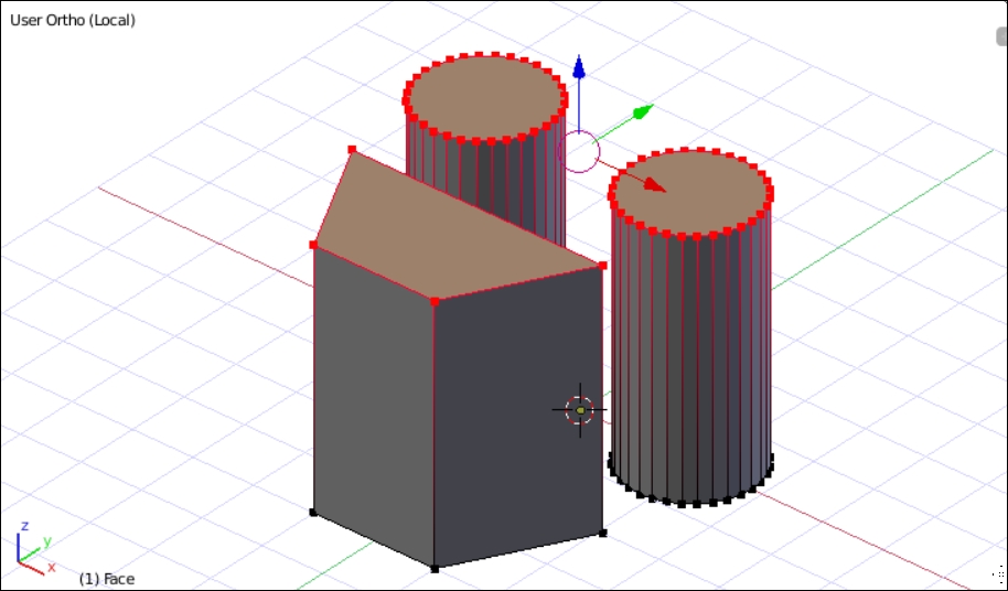
- Exit the Edit Mode (Tab). The face template is now complete, and it just needs to be scaled and positioned.
- Rotate (R) the face object around the x axis (X) by 90 degrees (90):
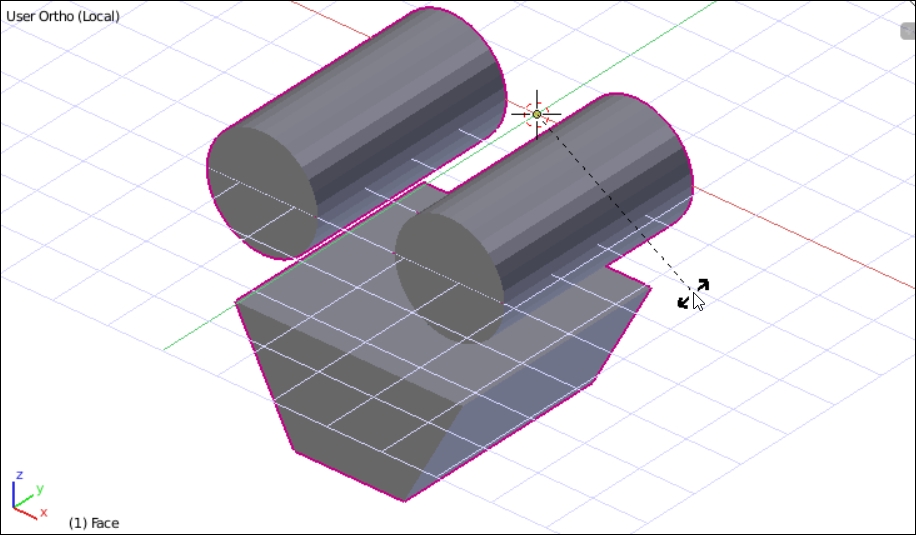
- Exit the local view (Numpad /). The face is hidden inside the body, so move (G) it in the z and y axes (Shift + X) until it's outside the octopus body:
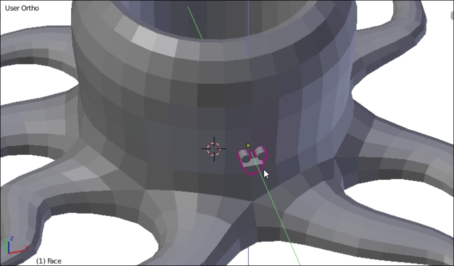
- In front of the Ortho view (NumPad 1), scale the face (S) and move (G) it in the z axis (Z) until it's positioned properly:

- In the side Ortho view (Numpad 3), move (G) the face along the y axis (Y) until it's partway into the body:
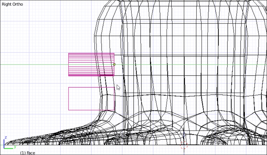
It may help to use the Wireframe view to ensure that the face is deep enough but not too deep. About four or five small squares (or 0.4 or 0.5 real-world millimeters) is perfect. If the face is too deep, it may cut all the way through into the cup space and may create an overhang problem. The top of the mouth will rely on some bridging during printing, and that's okay.
- Now, select the body, and in the Modifier tab, add a Boolean modifier. Change the settings of the Boolean modifier to be a Difference operation with the Face Object.
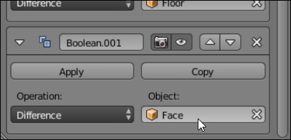
- The effect of this new modifier won't be visible immediately, so select the face object and hide it (H):
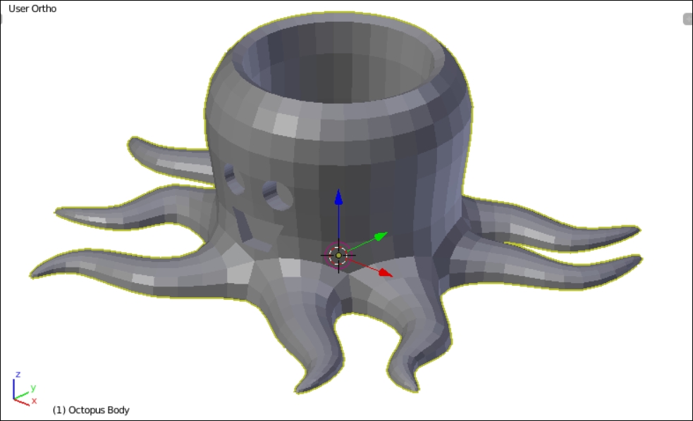
Your octopus pencil holder is now complete.
- Select the body, and in the Info panel menu (at the top of the screen), navigate to File | Export | Stl (.stl) to view the 3D-print-ready octopus holder. Ensure that you choose a directory where you can find the file later in order to send it to the printer:
