Modeling a simple part with the Draft workbench (Must know)
Many 3D designs begin as two dimensional drawings that are extruded or rotated into the third dimension. For example, a two dimensional square can be extruded into a three dimensional cube. The Draft workbench provides tools for working with 2D geometry.
In this recipe, we'll draw and edit a 2D profile of a part. In a later recipe, we'll rotate this profile to create a 3D model of a timing pulley.
Getting ready
Start a new project and switch to the Draft workbench. Make sure your view is set to top.
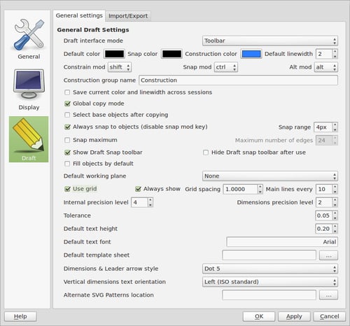
Change your draft preferences to make it easier to snap to the grid. Set the Grid spacing value to 1.000 and the Main lines every value to 10. Set the Snap range to about 4px.

How to do it...
Select the wire tool. Deselect the Relative checkbox. Points of a wire can be added by clicking the canvas or manually by keying in coordinates. Manually enter the first point at X = 3.175, Y = -5, and Z = 0. You can Tab from field to field and hit Enter on Z to create the point.
Continue adding a second point at X = 3.175, Y = 10, Z = -0.
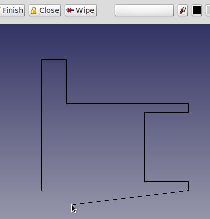
Enter the remaining points working clockwise around until your wire looks like the following image. The remaining points can be added by clicking the canvas, and snapping to the grid if you prefer. Holding the Shift key will force new segments to be orthogonal.
When you have entered the last point but before returning to the starting point, click on Close to automatically close the wire and exit the tool:

Before we can edit any part of the wire we have to explode it into a collection of edges. Select the wire in the project tree. Select the Draft menu and click on the Downgrade button three times.
We'll replace the square edge of the rim with a arc. Make sure that midpoint and endpoint are enabled on the snapping toolbar. Use the arc tool and draw a curve on the rim.

Repeat for the other rim, then delete the old straight edges.
Select all the edges in the tree. Select the Draft menu and click on the Upgrade button to rejoin them into a wire.
How it works...
Complex topological shapes are built up from more simple geometric objects such as lines, circles, and arcs. For example, an edge can be made from a line connecting two vertices, each of which is a just a point in space. An edge can also be an arc or a circle. When multiple edges are connected end-to-end they become a wire. A closed wire can be upgraded to a face, and if a collection of faces fully encloses a volume it is a solid. If a group of faces doesn't fully enclose the space (that is, one or more faces are missing) it is called a shell.
The Draft workbench provides tools for directly creating, modifying, and converting between these data types.
There's more....
In addition to the tools for creating and modifying 2D geometry, recent versions of the Draft workbench have a couple of powerful and useful features.
Create arrays
The array tool creates arrays of individual objects. Polar arrays are useful for creating bolt circles and gears. Ortho arrays create grid-like arrangements.

Select the object to be duplicated and click on the array tool. Then adjust the properties of the array in the Data tab. These include the number of copies, rotation center, and array type.
Converting drafts and sketches
A sketch is another way of drawing 2D data in FreeCAD, which we'll be looking at in more detail in a later recipe. Sketches and drafts serve different purposes but it's sometimes desirable to convert between them. The Draft workbench has a tool for doing this conversion. Be aware that sketch-specific data will be lost when it's converted to a draft.


