Understanding the Geometry Node editor
The Geometry Node system makes use of the node tree design in Blender, like the material node editor. Much like the material node editor, the node system flows from left to right. Geometry Nodes can modify and create different types of geometry, such as the following:
- Meshes
- Curves
- Point clouds
- Volumes
- Instances
Let’s take an in-depth look at these terms.
A mesh is a structural build of a 3D model consisting of faces. 3D meshes make use of the three axis points, x, y, and z. A mesh is made up of vertices, which make up edges, which, in turn, make up faces.
A curve is a way to define paths in Blender; this can be used on multiple occasions. For example, if you want a camera to follow a specific path, this can be done with curves. These can also be modified, used, and created in the Geometry Node editor. This will be explained in Chapter 8, Editing Curves with Nodes.
A point cloud is a selection of scattered points around a mesh. These point clouds are only visible in the viewport and not in the render.
A volume is a semi-transparent effect that can also be experimented with in the Geometry Node editor. Volumes are usually used to create abstract effects in the Geometry Node editor but can also be used to create a foggy atmosphere in your scene.
An instance is best explained as a copy of the original mesh. This can be used to copy multiple objects around a mesh, much like we used to do with hair particles. This is mostly used to scatter rocks or grass onto a base mesh.
All of these datatypes will use the same connection type, a Geometry connection. This node connection is green. Let’s have a look at the input and output node connection of the Geometry Node system.
Exploring the standard Geometry Nodes blocks
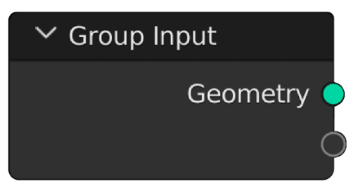
The first node that this book will introduce you to is the Group Input node.

Figure 1.2: Group Input node
The standard Geometry output of this node returns the base mesh of your object before any modifications have been made. This mesh basically returns the mesh you've inputted into the object's Edit mode.
This node is used to add variables to the Geometry Nodes Modifier so that you can have easy access to the most used variables. To create these variables, just slide a value into the unused node socket, and it will automatically occupy the node socket.
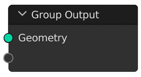
At the end of the node tree, you will use a Group Output node.

Figure 1.3: Group Output node
This will define the end of the Modifier. Just like the Group Input node, the Group Output node has an unused node socket to output extra data to the Modifier. This can be used to define UV maps, for example.


