Designing the solution
As we saw in the previous chapter, where we built our solution using VMs using AWS EC2, we had full control over the operating system configuration through the VM images we provisioned with Packer. Now that we will be transitioning to hosting our solution on AWS Elastic Kubernetes Service (EKS), we’ll need to introduce a new tool to replace VM images with container images – Docker:

Figure 8.1 – Logical architecture for the autonomous vehicle platform
Our application architecture, comprising a frontend, a backend, and a database, will remain the same, but we will need to provision different resources with Terraform and harness new tools from Docker and Kubernetes to automate the deployment of our solution to this new infrastructure:
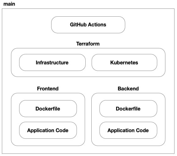
Figure 8.2 – Source control structure of our repository
In this solution, we’ll have seven parts. We still have the application code and Dockerfiles (replacing the Packer-based VM images) for both the frontend and backend. We still have GitHub Actions to implement our CI/CD process, but now we have two Terraform code bases – one for provisioning the underlying infrastructure to AWS and another for provisioning our application to the Kubernetes cluster hosted on EKS. Then, we have the two code bases for our application’s frontend and backend.
Cloud architecture
In the previous chapter, our cloud-hosting solution was a set of dedicated VMs. In this chapter, our objective is to leverage AWS EKS to use a shared pool of VMs that are managed by Kubernetes to host our application. To achieve this, we’ll be using some new resources that are geared toward container-based workloads. However, much of the networking, load balancing, and other components will largely be the same.
Virtual network
Recalling our work in Chapter 7 with EC2 instances and virtual networks, setting up a virtual private cloud (VPC) for AWS EKS follows a similar process. The core network is still there, with all the pomp and circumstance, from subnets – both public and private – to all the minutia of route tables, internet gateways, and NAT gateways, the virtual network we’ll build for our EKS cluster will largely be the same as the one we created previously. The only difference will be how we use it:
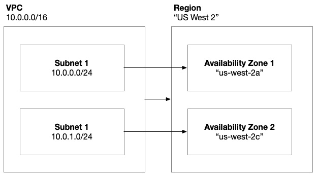
Figure 8.3 – AWS virtual network architecture
Previously, we used the public subnets for our frontend VMs and the private subnets for our backend. As we learned in Chapter 5, when we introduce Kubernetes into the mix, we’ll be transitioning to a shared pool of VMs that host our application as pods. These VMs will be hosted in the private subnets and a load balancer will be hosted in the public subnets.
Container registry
Building on our exploration of container architecture in Chapter 5, we know that we need to build container images and we need to store them in a container registry. For that purpose, AWS offers Elastic Container Registry (ECR). This is a private container registry, unlike public registries such as Docker Hub, which we looked at in Chapter 5.
We’ll need to utilize the Docker command-line utility to build and push images to ECR. To be able to do that, we need to grant an identity the necessary permissions. As we saw in the previous chapter, when we build VM images using Packer, we’ll likely have a GitHub Actions workflow that builds and pushes the container images to ECR. The identity that the GitHub Actions workflow executes under will need permission to do that. Once these Docker images are in ECR, the final step is to grant our cluster access to pull images from the registry:
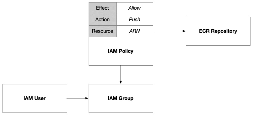
Figure 8.4 – IAM policy giving a group access to push container images to ECR
We’ll set up an IAM group that we’ll grant this permission to. This will allow us to add the user for the GitHub Action, as well as any other human users who want to push images directly from the command line. In AWS, IAM policies are extremely flexible; they can be declared independently or inline with the identity they are being attached to. This allows us to create reusable policies that can be attached to multiple identities. In this case, we’ll define the policy that grants access to push images to this ECR and then attach it to the group. Then, membership in the group will grant users access to these permissions.
The final step is to grant access to the cluster such that it can pull images from our ECR when it schedules pods within the nodes. To do that, we can use a built-in AWS policy called AmazonEC2ContainerRegistryReadOnly. We’ll need to reference it using its fully qualified ARN, which is arn:aws:iam::aws:policy/AmazonEC2ContainerRegistryReadOnly. Built-in policies have a common arn:aws:iam::aws:policy prefix that identifies them as published by AWS and not published by any specific user within their AWS account. When we publish our own policies, the fully qualified ARN will include our account number.
Load balancing
Unlike in the previous chapter, where we provisioned and configured our own AWS Application Load Balancer (ALB), when using Amazon EKS, one of the advantages is that EKS takes on much of the responsibility of provisioning and configuring load balancers. We can direct and influence its actions using Kubernetes annotations but this is largely taken care of for us. In our solution, to keep things simple, we’ll be using NGINX as our ingress controller and configuring it to set up an AWS Network Load Balancer (NLB) for us:
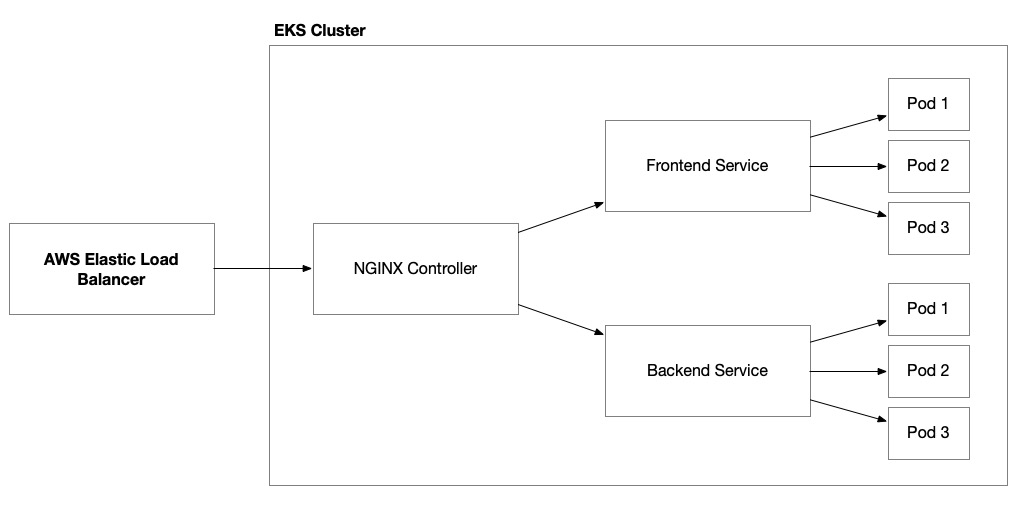
Figure 8.5 – Elastic load balancer working with an NGINX ingress controller to route traffic to our application’s pods
To delegate this responsibility to EKS, we need to grant it the necessary IAM permissions to provision and manage these resources. Therefore, we’ll need to provision an IAM policy and attach it to the EKS cluster. We can do this using an IAM role that has been assigned to the cluster’s node group:
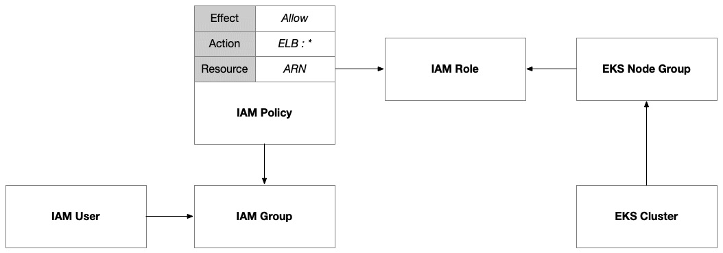
Figure 8.6 – IAM policy allowing EKS to provision and manage elastic load balancers
Then, we provision Kubernetes resources (for example, services and ingress controllers) and annotate them to inform the specific configuration of our elastic load balancers that we want EKS to enact on our behalf.
Network security
There are many ways to host services on Kubernetes and make them accessible outside of the cluster. In our solution, we’ll be using an AWS elastic load balancer to allow external traffic into our cluster through our NGINX controller. There are other options, such as NodePort, which allow you to access a pod directly through an exposed port on the node. This would require public access to the cluster’s nodes and is not the preferred method from both security and scalability perspectives.
If we want access to the cluster using kubectl, then we need to turn on public endpoint access. This is useful when you’re developing something small on your own but not ideal when you’re working in an enterprise context. You will most likely have the private network infrastructure in place so that you never have to enable the public endpoint.
Secrets management
Incorporating secrets into pods within an Amazon EKS cluster can be achieved through various methods, each with its advantages and disadvantages. As we did with VMs in the previous chapter, the method that we will explore is using AWS Secrets Manager secrets. Kubernetes has a built-in approach using Kubernetes Secrets. This method is straightforward and integrated directly into Kubernetes, but it has limitations in terms of security since secrets are encoded in Base64 and can be accessed by anyone with cluster access.
Integration with AWS Secrets Manager can help solve this problem but to access our secrets stored there, we need to enable our Kubernetes deployments to authenticate with AWS Identity and Access Management (IAM). This is often referred to as Workload Identity and it is an approach that is relatively common across cloud platforms:
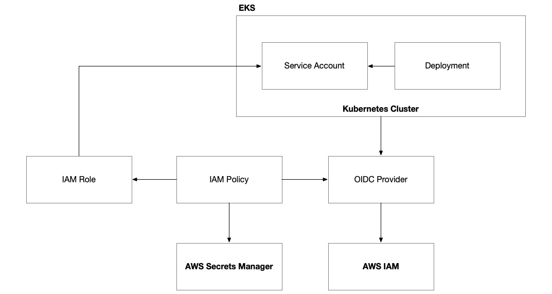
Figure 8.7 – AWS EKS with Workload Identity
To set up Workload Identity on EKS, we need to configure the cluster with an OpenID Connect (OIDC) provider. Then, we must set up an IAM role that has a policy that allows a Kubernetes service account to assume the role. This IAM role can then be granted access to any AWS permissions and resources that the Kubernetes deployment needs access to, including Secrets Manager secrets. The last thing we need to do is provision a Kubernetes service account by the same name within Kubernetes and give it a special annotation to connect it to the IAM role.
Once this is done, our Kubernetes deployments will be allowed to access our AWS Secrets Manager secrets but they won’t be using that access. The final step is to configure the Kubernetes deployment to pull in the secrets and make them accessible to our application code running in the pods:
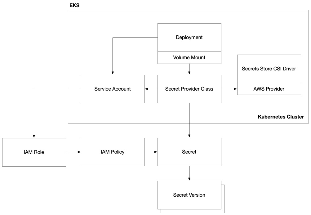
Figure 8.8 – AWS EKS Secrets Manager integration
Kubernetes has a common practice of doing this using volume mounts. As a result, there is a common Kubernetes provider known as the secrets store Container Storage Interface (CSI) provider. This is a cloud-agnostic technique that integrates Kubernetes with external secret stores, such as AWS Secrets Manager. This method offers enhanced security and scalability, but it requires more setup and maintenance.
To get this working, we need to deploy two components to our EKS cluster: the secrets store CSI driver and then the AWS provider for this driver that will allow it to interface with AWS Secrets Manager. Both of these components can be deployed to our EKS cluster with Helm. Once these important subsystems are in place, we can set up a special Kubernetes resource called SecretProviderClass. This is a type of resource that connects to AWS Secrets Manager through the CSI driver to access specific secrets. It connects to specific secrets in Secrets Manager using the service account that we granted access to via the IAM role and its permissions.
Kubernetes cluster
Amazon EKS offers a managed Kubernetes service that streamlines the deployment and management of containerized applications on AWS. The EKS cluster is the central figure of this architecture. EKS handles the heavy lifting of setting up, operating, and maintaining the Kubernetes control plane and nodes, which are essentially EC2 instances. When setting up an EKS cluster, users define node groups, which manifest as collections of EC2 instances that the EKS service is responsible for provisioning and managing.
There are several options for node groups that can host your workloads. The most common examples are AWS-managed and self-managed node groups. AWS-managed node groups are essentially on-demand EC2 instances that are allocated for the EKS cluster. AWS simplifies the management of these nodes but this imposes some restrictions on what AWS features can be used. Self-managed nodes are also essentially on-demand EC2 instances but they provide greater control over the features and configuration options available to them.
A great way to optimize for cost is to use a Fargate node group. This option takes advantage of AWS’ serverless compute engine and removes the need to provision and manage EC2 instances. However, this is probably more suitable for unpredictable workloads rather than those that require a steady state. In those situations, you can take advantage of a combination of autoscaling and spot and reserved instances to reap significant discounts and cost reduction:
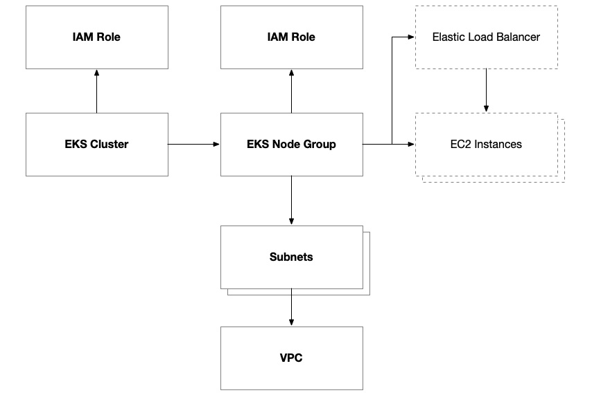
Figure 8.9 – Anatomy of an AWS EKS cluster
IAM policies are a major part of the configuration of EKS due to the nature of the service and how we delegate responsibility to it to manage AWS resources. This is similar to what we do with AWS Auto Scaling groups but even more so. IAM policies are attached to the cluster and individual node groups. Depending on the capabilities you want to enable within your cluster and your node groups, you might need additional policies.
The AmazonEKSClusterPolicy policy grants the cluster access to control the internal workings of the cluster itself, including node groups, CloudWatch logging, and access control within the cluster.
The AmazonEKSVPCResourceController policy grants the cluster access to manage network resources such as network interfaces, IP address assignment, and security group attachments to the VPC.
There are four policies (AmazonEKSWorkerNodePolicy, AmazonEKS_CNI_Policy, AmazonEC2ContainerRegistryReadOnly, and CloudWatchAgentServerPolicy) that are essential for the operation of EKS worker nodes. These policies absolutely must be attached to the IAM role that you assign to your EKS node group. They grant access to the EKS cluster’s control plane and let nodes within the node group integrate with the core infrastructure provided by the cluster, including the network, container registries, and CloudWatch. As described previously, we also added an optional policy to allow the EKS cluster to manage elastic load balancers.
Deployment architecture
Now that we have a good idea of what our cloud architecture is going to look like for our solution on AWS, we need to come up with a plan on how to provision our environments and deploy our code.
Cloud environment configuration
Building upon the methodology we established in Chapter 7 for provisioning EC2 instances, our approach to provisioning the AWS EKS environment will follow a similar pattern. The core of this process lies in utilizing GitHub Actions, which will remain unchanged in its fundamental setup and operation:
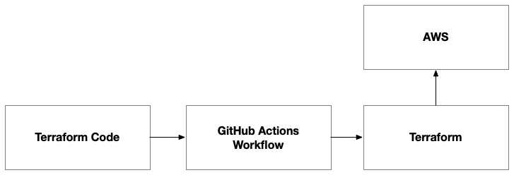
Figure 8.10 – The Terraform code provisions the environment on AWS
However, instead of provisioning EC2 instances as we did previously, the Terraform code will be tailored to set up the necessary components for an EKS environment. This includes the creation of an EKS cluster and an ECR. The GitHub Action will automate the execution of this Terraform code, following the same workflow pattern we used before.
By reusing the GitHub Actions workflow with different Terraform scripts, we maintain consistency in our deployment process while adapting to the different infrastructure requirements of the EKS environment. This step will need to be executed in a standalone mode to ensure certain prerequisites are there, such as the container registry. Only once the container registry is provisioned can we build and push container images to it for our frontend and backend application components.
This step will also provision the EKS cluster that hosts the Kubernetes control plane. We’ll use this in the final step in conjunction with the container images to deploy our application.
Container configuration
Unlike Packer, which doesn’t rely on any existing infrastructure to provision the application deployment artifacts (for example, the AMIs built by Packer), our container images need to have a container registry before they can be provisioned:

Figure 8.11 – Docker pipeline to build a container image for the frontend
The workflow is very similar to that of Packer in that we combine the application code and a template that stores the operating system configuration. In this case, it stores a Dockerfile rather than a Packer template.
Kubernetes configuration
Once we’ve published container images for both the frontend and backend, we’re ready to complete the deployment by adding a final step that executes Terraform using the Kubernetes provider so that it will deploy our application to the EKS cluster:
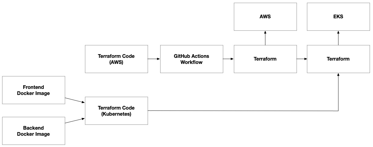
Figure 8.12 – Container images as inputs to terraform code, which provisions the environment on EKS’ Kubernetes control plane
We will output key pieces of information from the previous Terraform step that provisioned the AWS infrastructure. This will include details about the ECR repositories and the EKS cluster. We can use these as inputs for the final Terraform execution step where we use the Kubernetes provider. We have separated this step into separate Terraform workspaces to decouple it from the AWS infrastructure. This recognizes the hard dependency between the Kubernetes control plane layer and the underlying infrastructure. It allows us to independently manage the underlying infrastructure without making changes to the Kubernetes deployments, as well as make changes that are isolated within the Kubernetes control plane that will speed up the release process.
In this section, we reviewed the key changes in our architecture as we transitioned from VM-based architecture to container-based architecture. In the next section, we’ll get tactical in building the solution, but we’ll be careful to build on the foundations we built in the previous chapter when we first set up our solution on AWS using VMs powered by EC2.


