Pedestrian detection using HOG
The Histogram of Oriented Gradients (HOG) is an object detection technique implemented by OpenCV. In simple cases, it can be used to see whether there is a certain object present in the image, where it is, and how big it is.
OpenCV includes a detector trained for pedestrians, and you are going to use it. It might not be enough for a real-life situation, but it is useful to learn how to use it. You could also train another one with more images to see whether it performs better. Later in the book, you will see how to use deep learning to detect not only pedestrians but also cars and traffic lights.
Sliding window
The HOG pedestrian detector in OpenCV is trained with a model that is 48x96 pixels, and therefore it is not able to detect objects smaller than that (or, better, it could, but the box will be 48x96).
At the core of the HOG detector, there is a mechanism able to tell whether a given 48x96 image is a pedestrian. As this is not terribly useful, OpenCV implements a sliding window mechanism, where the detector is applied many times, on slightly different positions; the "image window" under consideration slides a bit. Once it has analyzed the whole image, the image window is increased in size (scaled) and the detector is applied again, to be able to detect bigger objects. Therefore, the detector is applied hundreds or even thousands of times for each image, which can be slow.
Using HOG with OpenCV
First, you need to initialize the detector and specify that you want to use the detector for pedestrians:
hog = cv2.HOGDescriptor()det = cv2.HOGDescriptor_getDefaultPeopleDetector()
hog.setSVMDetector(det)
Then, it is just a matter of calling detectMultiScale():
(boxes, weights) = hog.detectMultiScale(image, winStride=(1, 1), padding=(0, 0), scale=1.05)
The parameters that we used require some explanation, and they are as follows:
- The image
winStride, the window stride, which specifies how much the sliding window moves every time- Padding, which can add some padding pixels at the border of the image (useful to detect pedestrians close to the border)
- Scale, which specifies how much to increase the window image every time
You should consider that decreasing winSize can improve the accuracy (as more positions are considered), but it has a big impact on performance. For example, a stride of (4, 4) can be up to 16 times faster than a stride of (1, 1), though in practice, the performance difference is a bit less, maybe 10 times.
In general, decreasing the scale also improves the precision and decreases the performance, though the impact is not dramatic.
Improving the precision means detecting more pedestrians, but this can also increase the false positives. detectMultiScale() has a couple of advanced parameters that can be used for this:
hitThreshold, which changes the distance required from the Support Vector Machine (SVM) plane. A higher threshold means than the detector is more confident with the result.finalThreshold, which is related to the number of detections in the same area.
Tuning these parameters requires some experiments, but in general, a higher hitThreshold value (typically in the range 0–1.0) should reduce the false positives.
A higher finalThreshold value (such as 10) will also reduce the false positives.
We will use detectMultiScale() on an image with pedestrians generated by Carla:

Figure 1.8 – HOG detection, winStride=(1, 2), scale=1.05, padding=(0, 0)Left: hitThreshold = 0, finalThreshold = 1; Center: hitThreshold = 0, finalThreshold = 3;Right: hitThreshold = 0.2, finalThreshold = 1
As you can see, we have pedestrians being detected in the image. Using a low hit threshold and a low final threshold can result in false positives, as in the left image. Your goal is to find the right balance, detecting the pedestrians but without having too many false positives.
Introduction to the camera
The camera is probably one of the most ubiquitous sensors in our modern world. They are used in everyday life in our mobile phones, laptops, surveillance systems, and of course, photography. They provide rich, high-resolution imagery containing extensive information about the environment, including spatial, color, and temporal information.
It is no surprise that they are heavily used in self-driving technologies. One reason why the camera is so popular is that it mirrors the functionality of the human eye. For this reason, we are very comfortable using them as we connect on a deep level with their functionality, limitations, and strengths.
In this section, you will learn about the following:
- Camera terminology
- The components of a camera
- Strengths and weaknesses
- Choosing the right camera for self-driving
Let's discuss each in detail.
Camera terminology
Before you learn about the components of a camera and its strengths and weaknesses, you need to know some basic terminology. These terms will be important when evaluating and ultimately choosing your camera for your self-driving application.
Field of View (FoV)
This is the vertical and horizontal angular portion of the environment (scene) that is visible to the sensor. In self-driving cars, you typically want to balance the FoV with the resolution of the sensor to ensure we see as much of the environment as possible with the least number of cameras. There is a trade space related to FoV. Larger FoV usually means more lens distortion, which you will need to compensate for in your camera calibration (see the section on camera calibration):
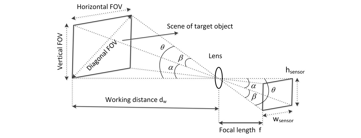
Figure 1.9 – Field of View, credit: https://www.researchgate.net/figure/Illustration-of-camera-lenss-field-of-view-FOV_fig4_335011596
Resolution
This is the total number of pixels in the horizontal and vertical directions on the sensor. This parameter is often discussed using the term megapixels (MP). For example, a 5 MP camera, such as the FLIR Blackfly, has a sensor with 2448 × 2048 pixels, which equates to 5,013,504 pixels.
Higher resolutions allow you to use a lens with a wider FoV but still provide the detail needed for running your computer vision algorithms. This means you can use fewer cameras to cover the environment and thereby lower the cost.
The Blackfly, in all its different flavors, is a common camera used in self-driving vehicles thanks to its cost, small form, reliability, robustness, and ease of integration:

Figure 1.10 – Pixel resolution
Focal length
This is the length from the lens optical center to the sensor. The focal length is best thought of as the zoom of the camera. A longer focal length means you will be zoomed in closer to objects in the environment. In your self-driving car, you may choose different focal lengths based on what you need to see in the environment. For example, you might choose a relatively long focal length of 100 mm to ensure enough resolution for your classifier algorithm to detect a traffic signal at a distance far enough to allow the car to react with smooth and safe stopping:

Figure 1.11 – Focal length, credit: https://photographylife.com/what-is-focal-length-in-photography
Aperture and f-stop
This is the opening through which light passes to shine on the sensor. The unit that is commonly used to describe the size of the opening is the f-stop, which refers to the ratio of the focal length over the aperture size. For example, a lens with a 50 mm focal length and an aperture diameter of 35 mm will equate to an f-stop of f/1.4. The following figure illustrates different aperture diameters and their f-stop values on a 50 mm focal length lens. Aperture size is very important in your self-driving car as it is directly correlated with the Depth of Field (DoF). Large apertures also allow the camera to be tolerant of obscurants (for example, bugs) that may be on the lens. Larger apertures allow light to pass around the bug and still make it to the sensor:

Figure 1.12 – Aperture, credit: https://en.wikipedia.org/wiki/Aperture#/media/File:Lenses_with_different_apertures.jpg
Depth of field (DoF)
This is the distance range in the environment that will be in focus. This is directly correlated to the size of the aperture. Generally, in self-driving cars, you will want a deep DoF so that everything in the FoV is in focus for your computer vision algorithms. The problem is that deep DoF is achieved with a small aperture, which means less light impacting the sensor. So, you will need to balance DoF with dynamic range and ISO to ensure you see everything you need to in your environment.
The following figure depicts the relationship between DoF and aperture:

Figure 1.13 – DoF versus aperture, credit: https://thumbs.dreamstime.com/z/aperture-infographic-explaining-depth-field-corresponding-values-their-effect-blur-light-75823732.jpg
Dynamic range
This is a property of the sensor that indicates its contrast ratio or the ratio of the brightest over the darkest subjects that it can resolve. This may be referred to using the unit dB (for example, 78 dB) or contrast ratio (for example, 2,000,000/1).
Self-driving cars need to operate both during the day and at night. This means that the sensor needs to be sensitive enough to provide useful detail in dark conditions while not oversaturating when driving in bright sunlight. Another reason for High Dynamic Range (HDR) is the example of driving when the sun is low on the horizon. I am sure you have experienced this while driving yourself to work in the morning and the sun is right in your face and you can barely see the environment in front of you because it is saturating your eyes. HDR means that the sensor will be able to see the environment even in the face of direct sunlight. The following figure illustrates these conditions:
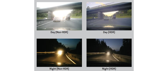
Figure 1.14 – Example HDR, credit: https://petapixel.com/2011/05/02/use-iso-numbers-that-are-multiples-of-160-when-shooting-dslr-video/
Your dream dynamic range
If you could make a wish and have whatever dynamic range you wanted in your sensor, what would it be?
International Organization for Standardization (ISO) sensitivity
This is the sensitivity of the pixels to incoming photons.
Wait a minute, you say, do you have your acronym mixed up? It looks like it, but the International Organization for Standardization decided to standardize even their acronym since it would be different in every language otherwise. Thanks, ISO!
The standardized ISO values can range from 100 to upward of 10,000. Lower ISO values correspond to a lower sensitivity of the sensor. Now you may ask, "why wouldn't I want the highest sensitivity?" Well, sensitivity comes at a cost...NOISE. The higher the ISO, the more noise you will see in your images. This added noise may cause trouble for your computer vision algorithms when trying to classify objects. In the following figure, you can see the effect of higher ISO values on noise in an image. These images are all taken with the lens cap on (fully dark). As you increase the ISO value, random noise starts to creep in:
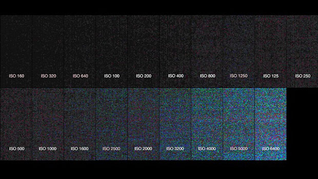
Figure 1.15 – Example ISO values and noise in a dark room
Frame rate (FPS)
This is the rate at which the sensor can obtain consecutive images, usually expressed in Hz or Frames Per Second (FPS). Generally speaking, you want to have the fastest frame rate so that fast-moving objects are not blurry in your scene. The main trade-off here is latency: the time from a real event happening until your computer vision algorithm detects it. The higher the frame rate that must be processed, the higher the latency. In the following figure, you can see the effect of frame rate on motion blur.
Blur is not the only reason for choosing a higher frame rate. Depending on the speed of your vehicle, you will need a frame rate that will allow the vehicle to react if an object suddenly appears in its FoV. If your frame rate is too slow, by the time the vehicle sees something, it may be too late to react:

Figure 1.16 – 120 Hz versus 60 Hz frame rate, credit: https://gadgetstouse.com/blog/2020/03/18/difference-between-60hz-90hz-120hz-displays/
Lens flare
These are the artifacts of light from an object that impact pixels on the sensor that do not correlate with the position of the object in the environment. You have likely experienced this driving at night when you see oncoming headlights. That starry effect is due to light scattered in the lens of your eye (or camera), due to imperfections, leading some of the photons to impact "pixels" that do not correlate with where the photons came from – that is, the headlights. The following figure shows what that effect looks like. You can see that the starburst makes it very difficult to see the actual object, the car!

Figure 1.17 – Lens flare from oncoming headlights, credit: https://s.blogcdn.com/cars.aol.co.uk/media/2011/02/headlights-450-a-g.jpg
Lens distortion
This is the difference between the rectilinear or real scene to what your camera image sees. If you have ever seen action camera footage, you probably recognized the "fish-eye" lens effect. The following figure shows an extreme example of the distortion from a wide-angle lens. You will learn to correct this distortion with OpenCV:
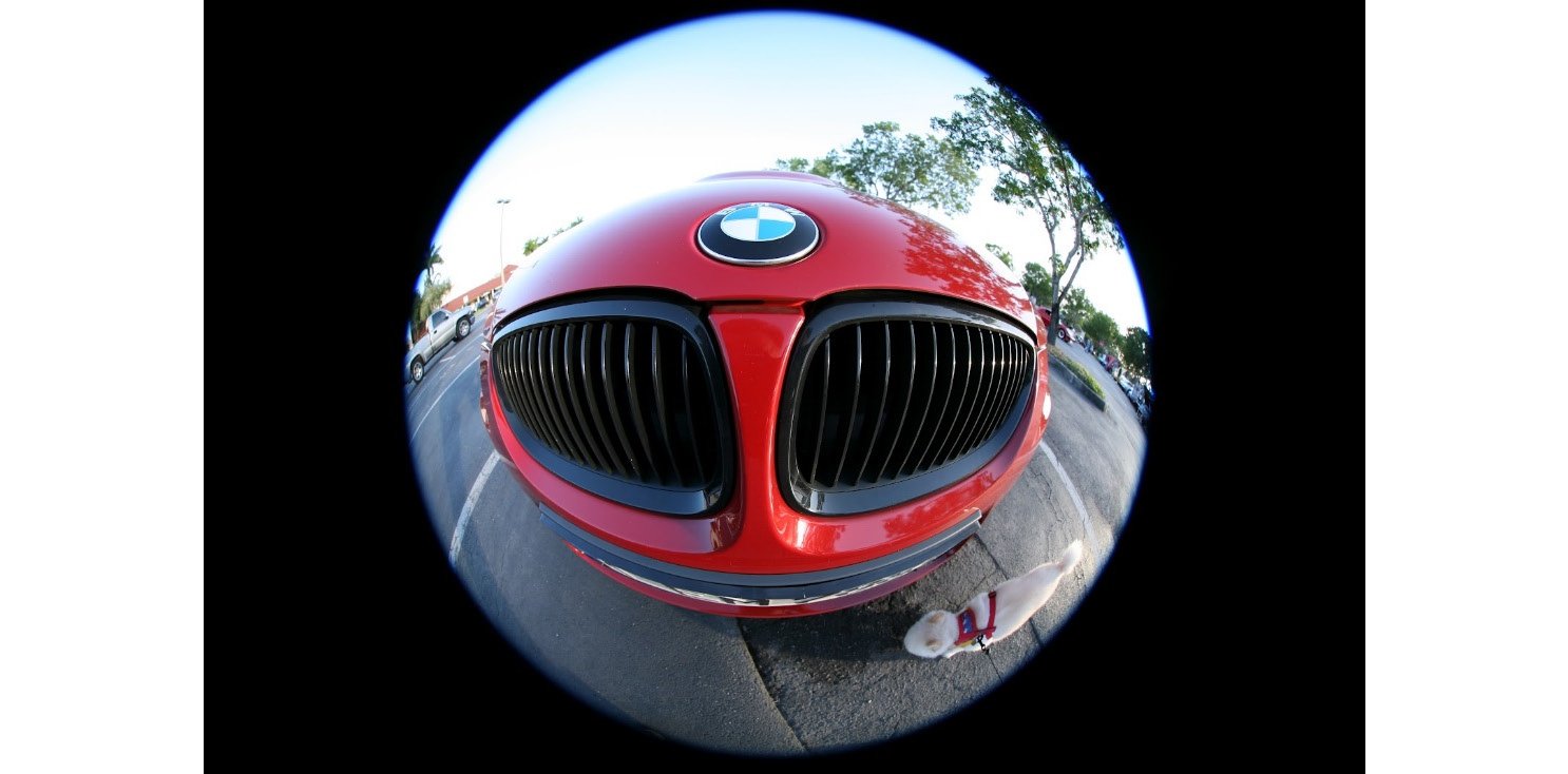
Figure 1.18 – Lens distortion, credit: https://www.slacker.xyz/post/what-lens-should-i-get
The components of a camera
Like the eye, a camera is made up of a light-sensitive array, an aperture, and a lens.
Light sensitive array – CMOS sensor (the camera's retina)
The light-sensitive array, in most consumer cameras, is called a CMOS active-pixel sensor (or just a sensor). Its basic function is to convert incident photons into an electrical current that can be digitized based on the color wavelength of the photon.
The aperture (the camera's iris)
The aperture or iris of a camera is the opening through which light can pass on its way to the sensor. This can be variable or fixed depending on the type of camera you are using. The aperture is used to control parameters such as depth of field and the amount of light hitting the sensor.
The lens (the camera's lens)
The lens or optics are the components of the camera that focus the light from the environment onto the sensor. The lens primarily determines the FoV of the camera through its focal length. In self-driving applications, the FoV is very important since it determines how much of the environment the car can see with a single camera. The optics of a camera are often some of the most expensive parts and have a large impact on image quality and lens flare.
Considerations for choosing a camera
Now that you have learned all the basics of what a camera is and the relevant terminology, it is time to learn how to choose a camera for your self-driving application. The following is a list of the primary factors that you will need to balance when choosing a camera:
- Resolution
- FoV
- Dynamic range
- Cost
- Size
- Ingress protection (IP rating)
The perfect camera
If you could design the ideal camera, what would it be?
My perfect self-driving camera would be able to see in all directions (spherical FoV, 360º HFoV x 360º VFoV). It would have infinite resolution and dynamic range, so you could digitally resolve objects at any distance in any lighting condition. It would be the size of a grain of rice, completely water- and dustproof, and would cost $5! Obviously, this is not possible. So, we must make some careful trade-offs for what we need.
The best place to start is with your budget for cameras. This will give you an idea of what models and specifications to look for.
Next, consider what you need to see for your application:
- Do you need to be able to see a child from 200 m away while traveling at 100 km/h?
- What coverage around the vehicle do you need, and can you tolerate any blind spots on the side of the vehicle?
- Do you need to see at night and during the day?
Lastly, consider how much room you have to integrate these cameras. You probably don't want your vehicle to look like this:
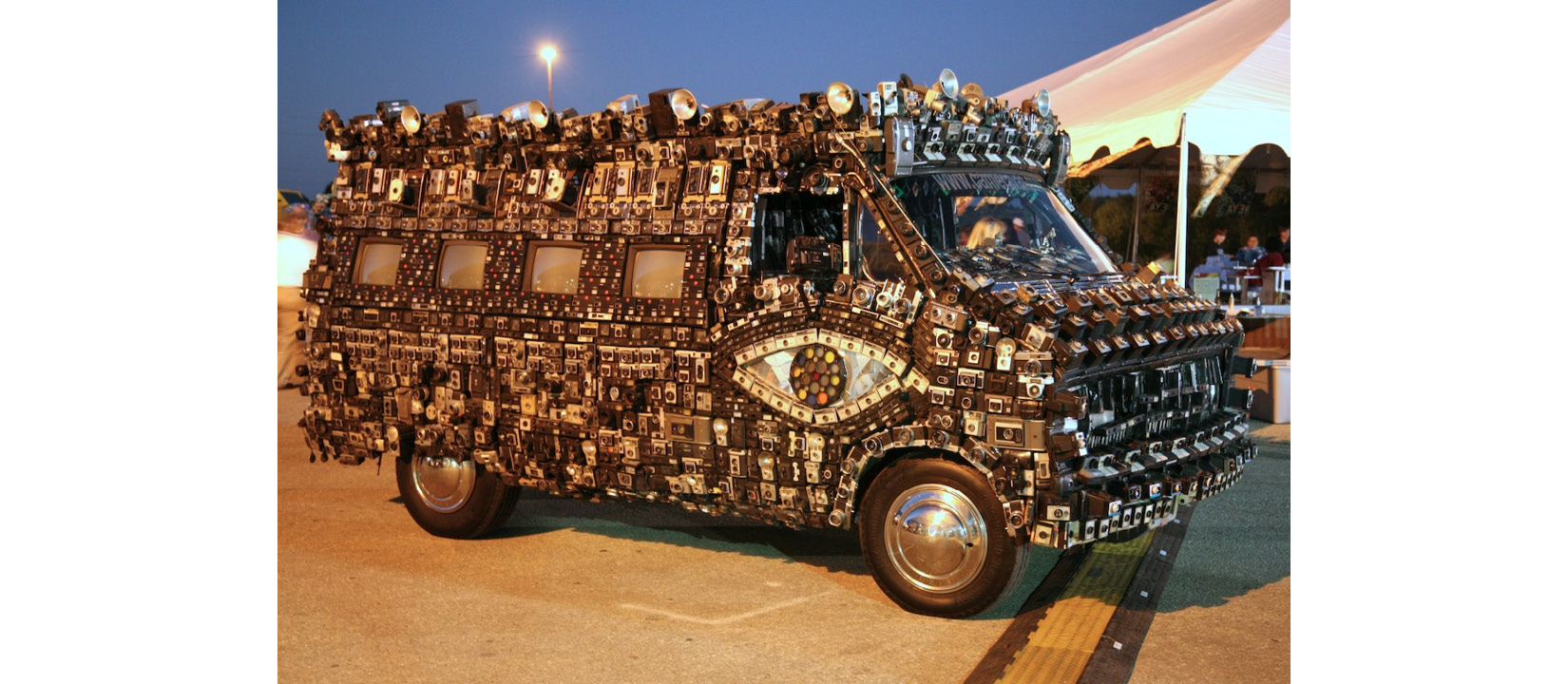
Figure 1.19 – Camera art, credit: https://www.flickr.com/photos/laughingsquid/1645856255/
This may be very overwhelming, but it is important when thinking about how to design your computer vision system. A good camera to start with that is very popular is the FLIR Blackfly S series. They strike an excellent balance of resolution, FPS, and cost. Next, pair it with a lens that meets your FoV needs. There are some helpful FoV calculators available on the internet, such as the one from http://www.bobatkins.com/photography/technical/field_of_view.html.
Strengths and weaknesses of cameras
Now, no sensor is perfect, and even your beloved camera will have its pros and cons. Let's go over some of them now.
Let's look at the strengths first:
- High-resolution: Relative to other sensor types, such as radar, lidar, and sonar, cameras have an excellent resolution for picking out objects in your scene. You can easily find cameras with 5 MP resolution quite cheaply.
- Texture, color, and contrast information: Cameras provide very rich information about the environment that other sensor types just can't. This is because of a variety of wavelengths that cameras sense.
- Cost: Cameras are one of the cheapest sensors you can find, especially for the quality of data they provide.
- Size: CMOS technology and modern ASICs have made cameras incredibly small, many less than 30 mm cubed.
- Range: This is really thanks to the high resolution and passive nature of the sensor.
Next, here are the weaknesses:
- A large amount of data to process for object detection: With high resolution comes a lot of data. Such is the price we pay for such accurate and detailed imagery.
- Passive: A camera requires an external illumination source, such as the sun, headlights, and so on.
- Obscurants (such as bugs, raindrops, heavy fog, dust, or snow): A camera is not particularly good at seeing through heavy rain, fog, dust, or snow. Radars are typically better suited for this.
- Lack native depth/velocity information: A camera image alone doesn't give you any information on an object's speed or distance.
Photogrammetry is helping to bolster this weakness but costs valuable processing resources (GPU, CPU, latency, and so on.) It is also less accurate than a radar or lidar sensor, which produce this information natively.
Now that you have a good understanding of how a camera works, as well as its basic parts and terminology, it's time to get your hands dirty and start calibrating a camera with OpenCV.


