Deep dive into the Arduino IDE 2.0 to program ESP32
In this section, we will discuss the ESP32 board and its programming using the Arduino IDE 2.0. As discussed in the previous section, ESP32 is a powerful microcontroller and can be programmed in several ways. We will discuss some common ways in which we can program ESP32 and discuss why the Arduino IDE is a beginner-friendly IDE to get started with ESP32. We will have a brief introduction to the Arduino IDE, install the Arduino IDE, and will get ourselves familiarized with the Arduino IDE user interface. Then, we will move on to setting up the IDE for programming ESP32, and finally, we will walk through a simple “Hello World” example using an LED to demonstrate the basics of ESP32 programming with the Arduino IDE.
How can ESP32 be programmed?
ESP32 can be programmed in several ways, including the Arduino IDE, the Python programming language, the Expressif-IoT Development Framework (ESP-IDF, the official development framework by Espressif), and many more. Some of the most common and widely used methods are described as follows:
- Arduino IDE: A beginner-friendly IDE that can help you write, compile, and upload code to ESP32 using the Arduino programming language.
- MicroPython: A Python-based interpreter that runs on ESP32, allowing developers to write Python code and execute it directly on the device.
- ESP-IDF: The official development framework for ESP32 offers several APIs for low-level hardware access and allows for more flexibility in programming and debugging.
- Other programming options: Other ways can be used to program ESP32, such as Visual Studio Code with PlatformIO, JavaScript and Node.js, and Rust.
The following table differentiates the three most common options for programming:
|
Parameter |
Arduino IDE |
MicroPython |
ESP-IDF |
|
Language |
C++ |
Python |
C |
|
IDE support |
Yes |
No |
No |
|
Community support |
High |
Moderate |
High |
|
Low-level access |
Limited |
Limited |
Full |
|
Learning curve |
Easy |
Easy |
Moderate |
Table 1.1 – Comparison of programming options for ESP32
Table 1.1 compares the three most common options for programming ESP32. The Arduino IDE and MicroPython are beginner-friendly options, while ESP-IDF provides you complete access to the functionalities of ESP32. However, the absence of IDE support in ESP-IDF and MicroPython makes it difficult for beginners to get started.
The Arduino IDE 2.0
The Arduino IDE 2.0 is the latest version of the popular open source software (OSS) for programming Arduino boards. The IDE is an easy-to-use platform for programming microcontrollers and creating interactive electronic projects. It has many new features as compared to the previous versions, it is more user-friendly and powerful, and you can use and manage libraries (libraries are pre-written code modules that simplify the development of Arduino projects by providing functions for various tasks), boards, and projects in a single place, making it easier to find and organize your work.
It is an official software for programming Arduino boards, but you can add support for other boards such as ESP32, ESP8266, Network Repository Function (NRF) boards, and Synchronous Transport Module (STM) boards, and its user-friendly interface helps beginner-level developers get started easily.
Installing the Arduino IDE 2.0
Installing the Arduino IDE 2.0 is a very straightforward process that is like installing any other software. Following are summarized steps you can follow to install the Arduino IDE 2.0 on your system:
- Go to the Arduino software page on the Arduino website (https://www.arduino.cc/en/software).
- Scroll down to the download options and select an option based on your operating system:
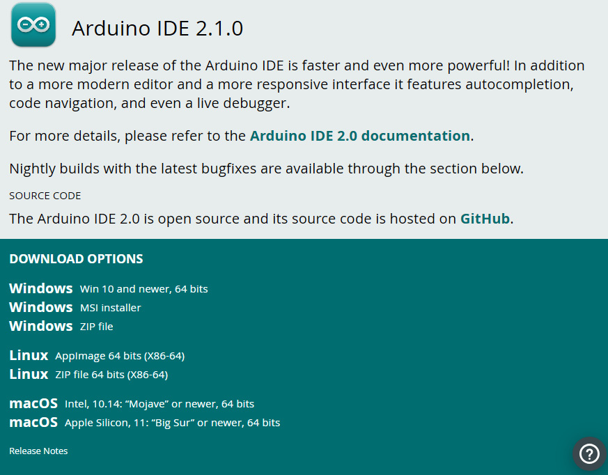
Figure 1.3 – Arduino IDE download options
- For Windows, run the installer and follow the prompt. For Linux, extract the downloaded file and run the
arduino -idescript. For macOS, open the downloaded.dmgfile and drag the application’s Arduino IDE 2.0 icon into the application folder.
Important note
Depending on your system configuration, you may need to install additional dependencies or drivers. Refer to the Arduino installation documentation (https://docs.arduino.cc/software/ide-v2/tutorials/getting-started/ide-v2-downloading-and-installing) or Arduino Forum for more details.
Hopefully, you have successfully installed the Arduino IDE, and in the next section, we will have an overview of the Arduino IDE user interface.
An overview of the Arduino IDE 2.0 user interface
The IDE 2.0 is divided into four main sections: the menu bar, the left sidebar, the editor area, and the bottom panel. The menu bar provides access to all functions and tools available in the IDE, including opening and saving files, compiling code, and uploading it to the board:
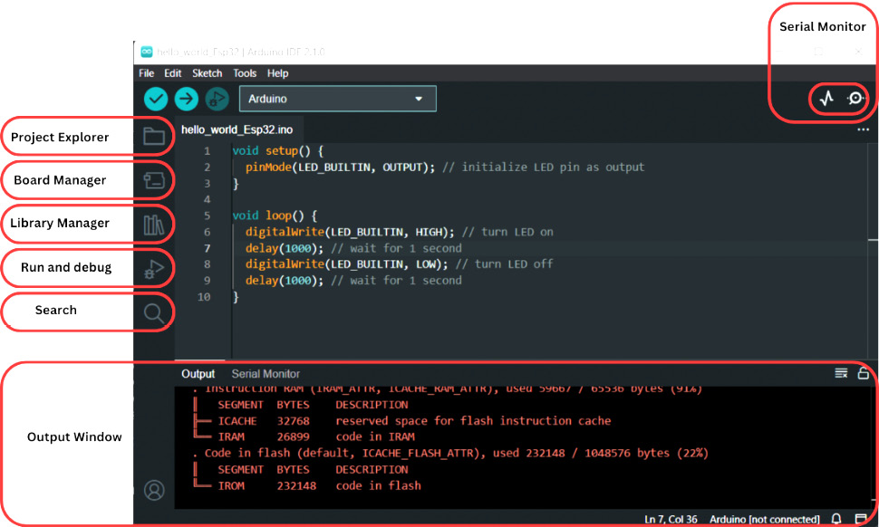
Figure 1.4 – Overview of the Arduino IDE 2.0 user interface
The left sidebar contains the project explorer, which shows the structure of the project, the board manager, which can help you install new boards’ support, the library manager, which will help you to include, search for, and install new libraries, and debugger and search options, which help while writing code and debugging errors.
The editor area is where code is written and edited, and features such as syntax highlighting and autocompletion make it easy to write code.
The bottom panel displays the console output, debugging information, and serial monitor, which we will be using a lot in upcoming chapters for debugging our code.
Setting up the Arduino IDE 2.0 for ESP32
To use ESP32 in the Arduino IDE, we will first have to install the ESP32 board support, which helps us to compile, build, and upload the ESP32 program. The board support can be installed using the following steps:
- Once the Arduino IDE is installed, launch Arduino IDE.
- Go to File | Preferences…:
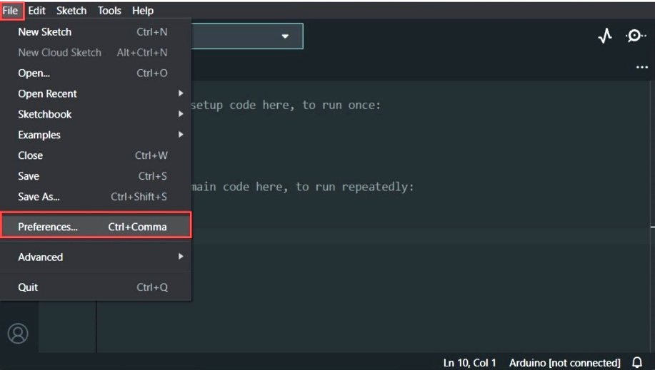
Figure 1.5 – Preferences in the Arduino IDE
- Paste the following link into the Additional boards manager URLs section: https://raw.githubusercontent.com/espressif/arduino-esp32/gh-pages/package_esp32_index.json
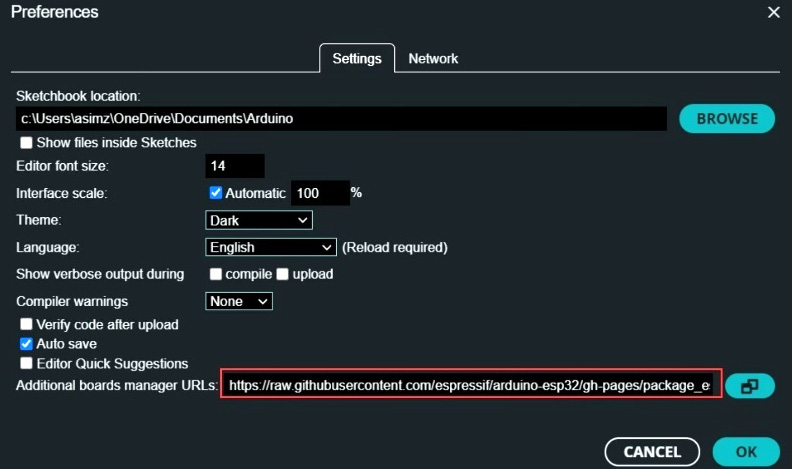
Figure 1.6 – Pasting URL into the Additional boards manager URLs section
- After adding the URL to the Additional boards manager URLs section, go to BOARDS MANAGER, which can be accessed from the left-hand side menu, type
esp32, and install the board support:
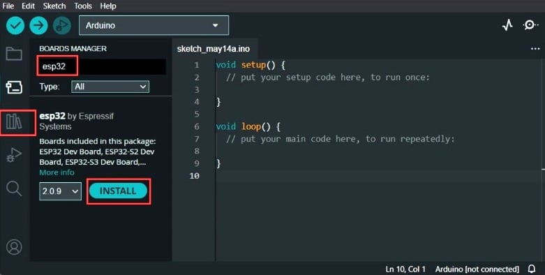
Figure 1.7 – Installing ESP32 board support in the Arduino IDE
- It will be installed in a few minutes, and you will see the results in the output window:
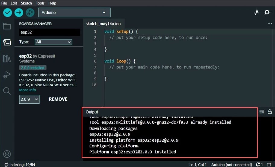
Figure 1.8 – ESP32 board support installed in the Arduino IDE
Important note
If you have multiple URLs in the Additional boards manager URLs section (for example, if you have ESP8266, NRF boards, or other boards support installed), you can separate the URLs using a comma between them.
You have now installed the board support for ESP32 and are ready to write and upload exciting IoT programs to ESP32 using the Arduino IDE. In the next part, we will write a “Hello World” example for ESP32.
ESP32 “Hello World” example using the Arduino IDE 2.0
In other programming languages, the Hello World program is the simplest program that serves as an introduction to the programming language and mostly prints “Hello World." In the case of ESP32 and the Arduino IDE, the equivalent to the Hello World program is a blinking LED as it is the simplest and most basic program to test the functionality of the board and its ability to communicate with the IDE. If the LED blink is successful, the developer can verify that the board and IDE are working as expected and can proceed to more complex projects.
You can follow the next steps to run the “Hello World” example:
- Open a new sketch by clicking File | New in the Arduino IDE.
- Type the following code in the new sketch:
void setup() {pinMode(LED_BUILTIN, OUTPUT);
}
void loop() {digitalWrite(LED_BUILTIN, HIGH);
delay(1000);
digitalWrite(LED_BUILTIN, LOW);
delay(1000);
}
The Hello World code is made up of two parts or functions: the
setup()function and theloop()function.The
setup()function runs only once when the ESP32 board is powered up or reset. In our previous code, we used thesetup()function to initialize the LED pin as an output.The
loop()function runs continuously after thesetup()function has been executed. In our last example, we first turn on the LED using thedigitalWrite()function and set the digital pin toHIGH. Then, using thedelay()function, we wait for1000milliseconds or 1 second before setting the state of the LED toOFFby setting the digital pin toLOWand wait for another short amount of time to use thedelay()function. The process is repeated, resulting in the LED blinking. - Make sure you have selected the right version of the ESP32 board and the correct COM port.
- Upload the sketch to the ESP32 board by clicking on the Upload button in the Arduino IDE and wait for the upload process to complete.
- Once the upload is complete, you will see the built-in LED in ESP32 should start blinking:
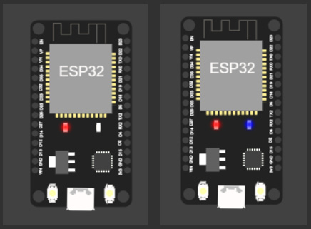
Figure 1.9 – Built-in LED state OFF (left ESP32) and built-in LED state ON (right ESP32)
Congratulations! You have run your first project using ESP32 and the Arduino IDE. You are on the right track to build exciting IoT projects. In the next section, you will learn a bonus skill; that is, simulating your project in a browser.
Bonus – Simulating ESP32 projects
This book is written to give you practical knowledge of ESP32 and encourages you to build projects using real hardware, but simulating ESP32 projects can be advantageous in several ways as compared to using actual hardware. Simulation can save costs and allows you to do rapid testing and debugging without hardware damage, and it provides an interactive way for beginners to learn and experiment with ESP32 and the Arduino IDE.
Let’s simulate the Hello World program in the ESP32 simulator. You could follow the next steps to simulate your ESP32 projects:
- Visit https://www.wokwi.com, which is an Arduino and ESP32 simulator and is designed to simulate IoT projects in a browser:
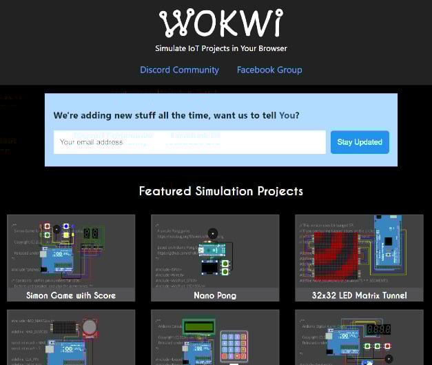
Figure 1.10 – Wokwi IoT simulator
- Sign up for a new account and then log in:
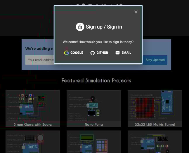
Figure 1.11 – Signing up for or signing in to Wokwi
- After logging in, navigate to https://wokwi.com/dashboard/projects and click on + NEW PROJECT:

Figure 1.12 – Creating a new project in Wokwi
- When it asks for boards, select ESP32 if you want to simulate using the Arduino programming language:
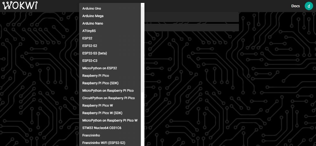
Figure 1.13 – Selecting the ESP32 board in Wokwi
- In the
sketch.inofile, paste the Hello World code:
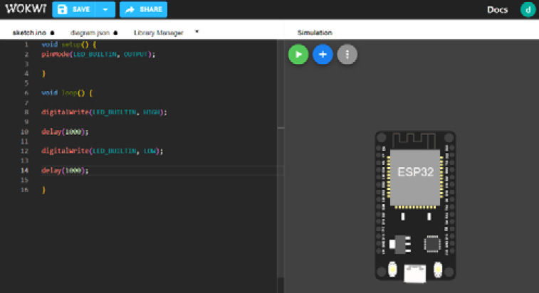
Figure 1.14 – Writing code in Wokwi
- Click on the green button that says Start the simulation, and you will see that the built-in LED will start blinking:
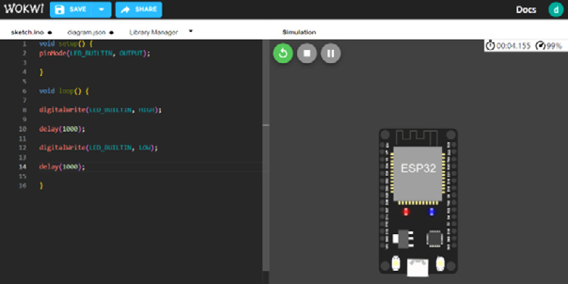
Figure 1.15 – Running a simulation in Wokwi
If you would like to add more parts, you can click on the blue + button, and you will see many peripheral options such as buttons, switches, LEDs, LCDs, different sensors, and so on:
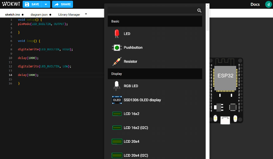
Figure 1.16 – Adding a new part in Wokwi
This simulation tool will help you debug code without actually making circuits. All the examples that we will perform in this book can be simulated using Wokwi.


