Model-based safety analysis
The term safety can be defined as freedom from harm. Safety is one of the three pillars of the more general concern of system dependability. Safety is generally considered with respect to the system causing or allowing physical harm to persons, up to and including death. Depending on the industry, different systems must conform to different safety standards, such as DO-178 (airborne software), ARP4761 (aerospace systems), IEC 61508 (electronic systems), ISO 26262 (automotive safety), IEC 63204 (medical), IEC 60601 (medical), and EN50159 (railway), just to name a few. While there is some commonality among the standards, there are also a number of differences that you must take into account when developing systems to comply with those standards.
This recipe provides a generic workflow applicable to all these standards, but you may want to tailor it for your specific needs. Note that we recommend this analysis is done on a per-use case basis so that the analysis of each relevant use case includes safety requirements in addition to the functional and quality of service requirements.
A little bit about safety analysis
Some key terms for safety analysis are as follows:
- Accident – A loss of some kind, such as injury, death, equipment damage, or financial. Also known as a mishap.
- Risk – The product of the likelihood of an accident and its severity.
- Hazard – A set of conditions and/or events that inevitably results in an accident.
- Fault tolerance time – the period of time a system can manifest a fault before an accident is likely to occur.
- Safety control measure – An action or mechanism that improves systems safety either by 1) reducing an accident, hazard, or risk's likelihood or 2) reducing its severity.
The terms faults, failures, and errors are generally used in one of three ways, depending on the standard employed:
- Faults lead to failures, which lead to errors:
a. Fault – An incorrect step, process, or data.
b. Failure – The inability of a system or component to perform its required function.
c. Error – A discrepancy between an actual value or action and the theoretically correct value or action.
d. A fault at one level can lead to a failure one level up.
- Faults are actual behaviors that are in conflict with specified or desired behaviors:
a. Fault – Either a failure or an error.
b. Failure – An event that occurs at a point in time when a system or component performs incorrectly.
- Failures are random and may be characterized with a probability distribution.
c. Error – A condition in which a system or component systematically fails to achieve its required function.
- Errors are systematic and always exist, even if they are not manifest.
- Errors are the result of requirement, design, implementation, or deployment mistakes, such as a software bug.
d. Manifest – When a fault is visible. Faults may be manifest or latent.
- Faults are undesirable anomalies in systems or software (ARP-4761):
Failure – A loss of function or a malfunction of a system
Error – The occurrence arising as a result of an incorrect action or decision by personnel operating or maintaining a system, or a mistake in the specification, design, or implementation
The most common way to perform the analysis is with a Fault Tree Analysis (FTA) diagram. This is a causality diagram that relates normal conditions and events, and abnormal conditions and events (such as faults and failures), with undesirable conditions (hazards). A Hazard Analysis is generally a summary of the safety analysis from one or more FTAs.
FTA
An FTA diagram connects nodes with logic flows to aid understanding of the interactions of elements relevant to the safety concept. Nodes are either events, conditions, outcomes, or logical operators, as shown in Figure 2.51. See https://www.sae.org/standards/content/arp4761/ for a good discussion of FTA diagrams:
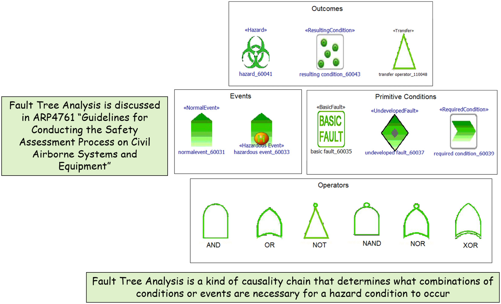
Figure 2.51 – FTA elements
The logical operators take one or more inputs and produce a singular output. The AND operator, for example, produces a TRUE output if both its inputs are TRUE, while the OR operator returns TRUE if either of its inputs is TRUE. There is also a TRANSFER operator, which allows an FTA diagram to be broken up into subdiagrams.
Figure 2.52 shows an example FTA diagram. This diagram shows the safety concerns around an automotive braking system. The hazard under consideration is Failure to Brake. The diagram shows that this happens when the driver intends to brake and at least one of three conditions is present: a pedal input fault, an internal fault, or a wheel assembly fault:
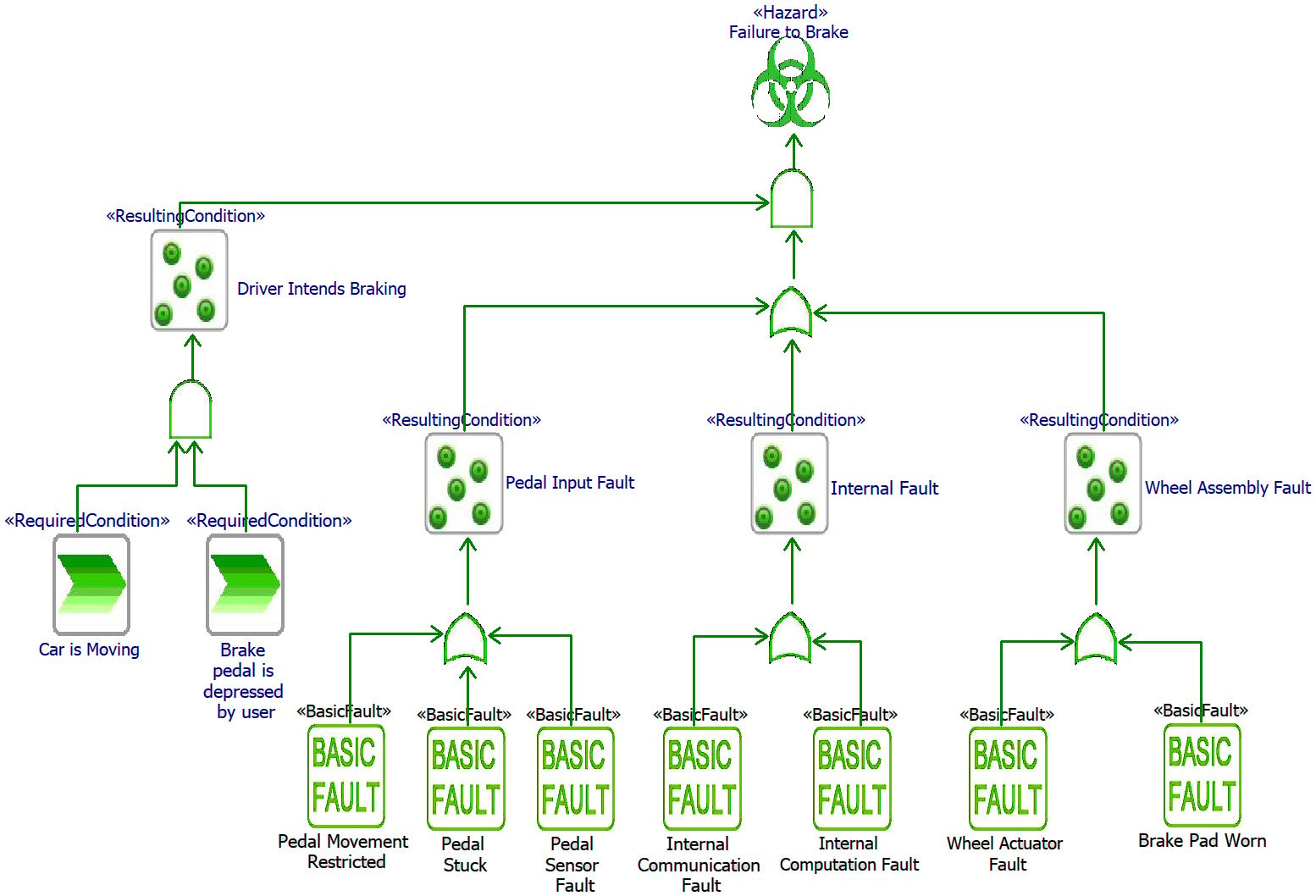
Figure 2.52 – Example FTA diagram
Cut sets
A cut is a collection of faults that, taken together, can lead to a hazard. A cut set is the set of such collections such that all possible paths from the primitive conditions and events to the hazard have been accounted for. In general, if you consider n primitive conditions as binary (present or non-present), then there are 2n cuts that must be examined. Consider the simple FTA in Figure 2.53. The primitive conditions are marked as a though e:
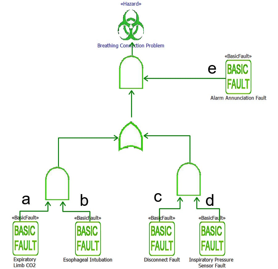
Figure 2.53 – Cut set example
With 5 primitive conditions, 32 prospective cut sets should be considered, of which only 3 can lead to the hazard manifestation, as shown in Figure 2.54. Only these three need to be subject to the addition of a safety measure:
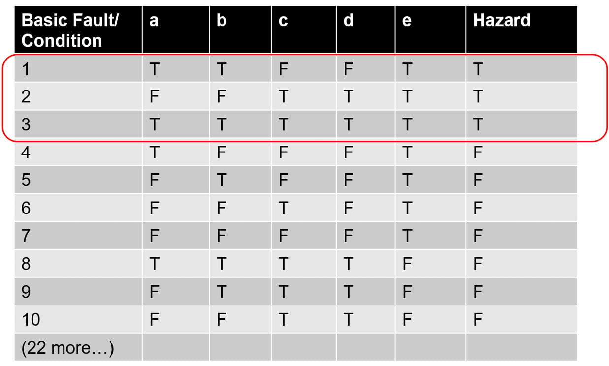
Figure 2.54 – Cut sets example (2)
Hazard analysis
There is normally one FTA diagram per identified hazard, although that FTA diagram can be decomposed into multiple FTA diagrams via the transfer operator. A system, however, normally has multiple hazards. These are summarized into a hazard analysis. A hazard analysis summarizes the hazard-relevant metadata, including the hazard name, description, severity, likelihood, risk, tolerance time, and possibly, related safety-relevant requirements and design elements.
UML Dependability Profile
I have developed a UML Dependability Profile that can be applied to UML and SysML models in the Rhapsody tool. It is free to download from https://www.bruce-douglass.com/safety-analysis-and-design. The ZIP repository includes instructions on the installation and use of the profile. All the FTA diagrams in this recipe were created in Rhapsody using this profile.
Purpose
The purpose of this recipe is to create a set of safety-relevant requirements for the system under development by analyzing safety needs.
Inputs and preconditions
A use case naming a capability of the system from an actor-use point of view that has been identified, described, and for which relevant actors have been identified. Note: this recipe is normally performed in parallel with one of the functional analysis recipes from earlier in this chapter.
Outputs and postconditions
The most important outcome is a set of requirements specifying how the system will mitigate or manage the safety concerns of the system. Additionally, a safety concept is developed identifying the needs for a set of safety control measures, which is summarized in a hazard analysis.
How to do it…
Figure 2.55 shows the workflow for the recipe:
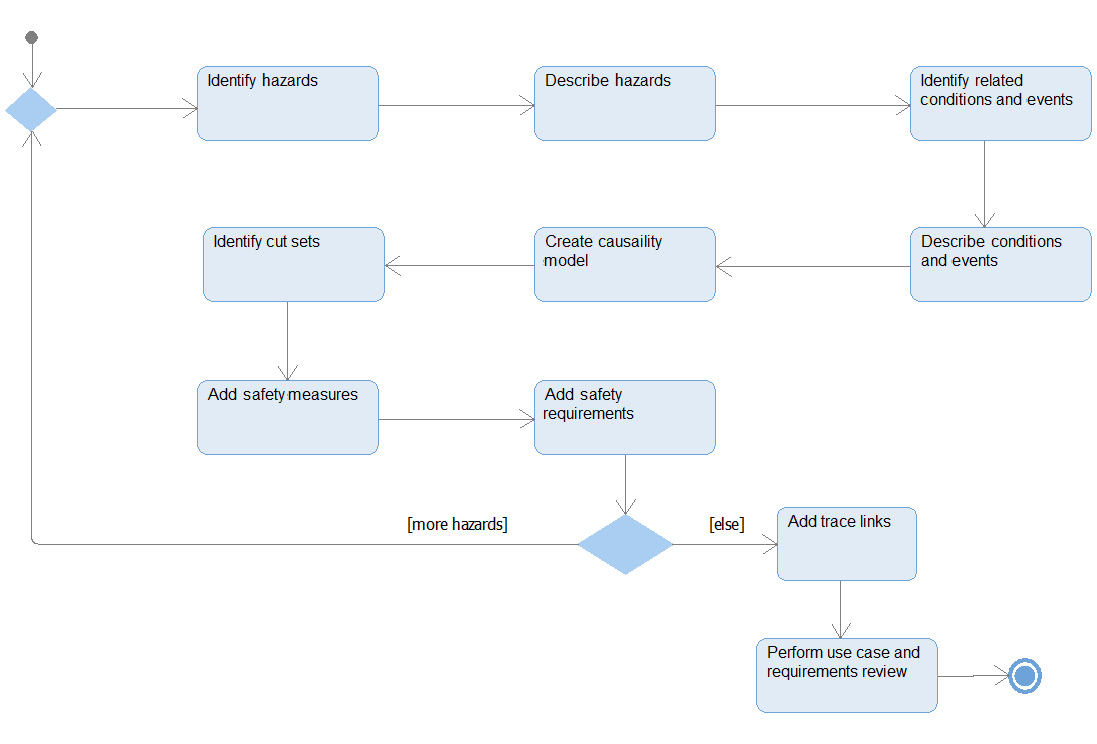
Figure 2.55 – Model-based safety analysis workflow
Identify the hazards
A hazard is a condition that can lead to an accident. This step identifies the hazards relevant to the use case under consideration that could arise from the system behavior in its operational context.
Describe the hazards
Hazards are specified by their safety-relevant metadata. This generally includes the hazard name, description, likelihood, severity, risk, and safety integrity level, adopted from the relevant safety standard.
Identify related conditions and events
This step identifies the conditions and events related to the hazard, including the following:
- Required conditions
- Normal events
- Hazardous events
- Fault conditions
- Resulting conditions
Describe conditions and events
Each condition and event should be described. A typical set of aspects of such a description includes the following:
- Overview
- Effect
- Cause
- Current controls
- Detection mechanisms
- Failure mode
- Likelihood or Mean Time Between Failure (MTBF)
- Severity
- Recommended action
- Risk priority (product of likelihood and severity or MTBF/severity)
Create a causality model
This step constructs an FTA connecting the various nodes with logic flows and logic operators flowing from primitive conditions up to resulting conditions and, ultimately, to the hazard.
Identify cut sets
Identify the relevant cuts from all possible cut sets to ensure that each is safe enough to meet the safety standard being employed. This typically requires the addition of safety measures, as discussed in the next step.
Add safety measures
Safety measures are technical means or usage procedures by which safety concerns are mitigated. All safety measures either reduce the likelihood or the severity of an accident. In this analysis, care should be taken to specify the effect of the measures rather than their implementation, as much as possible. Design-level hazard analysis will be conducted later to ensure the adequacy of the design realization of the safety measures specified here.
Review the safety concept
This step reviews the analysis and the set of safety measures to ensure their adequacy.
Add safety requirements
The safety requirements specify what the design, context, or usage must meet in order to be adequately safe. These requirements may be specially annotated to indicate their safety relevance or may just be treated as requirements that the system must satisfy.
Example
Let's see an example.
The Pegasus example problem isn't ideal for showing safety analysis because it isn't a safety-critical system. For that reason, we will use a different example for this recipe.
Problem statement – medical gas mixer
The Medical Gas Mixer (MGM) takes in gas from wall supplies for O2, He, N2, and air and mixes them and delivers a flow to a medical ventilator. When operational, the flow must be in the range of 100 ml/min to 1,500 ml/min with a delivered O2 percentage (known as the Fraction of Delivered Oxygen, or FiO2) of no less than 21%. The flows from the individual gas sources are selected by the physician via the ventilator's interface.
Neonates face an additional hazard of hyperoxia – too much oxygen in the blood, as this can damage their retinas and lungs.
In this example, the focus of our analysis is the Mix Gases use case.
Identify the hazards
The fundamental hazard of this system is hypoxia – delivering too little oxygen to sustain health. The average adult breathes about 7-8 liters of air per minute, resulting in a delivered oxygen flow of around 1,450 ml O2/minute. For neonates, required flow can be as low as 40 ml O2/minute, while for large adults the need might be as high as 4,000 ml O2/minute at rest.
Describe the hazards
The «Hazard» stereotype includes a set of tags for capturing the hazard metadata. This is shown in Figure 2.56:
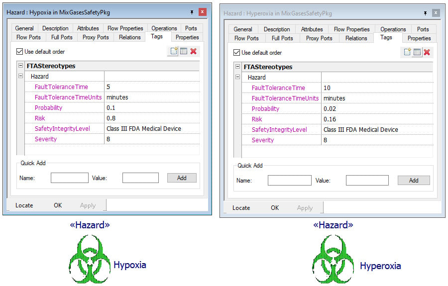
Figure 2.56 – Mix Gases hazards
Identify related conditions and events
For the rest of this example, we will focus exclusively on the Hypoxia hazard. There are two required conditions (or assumptions/invariants): first, that the gas mixer is in operation and second, that there is a physician in attendance. This latter assumption means that the physician can be part of the safety loop.
There a number of faults that are relevant to the Hypoxia hazard:
- The gas supply runs out of either air or O2, depending on which is selected.
- The gas supply valve fails for either air or O2, depending on which is selected.
- The patient is improperly intubated.
- A fault in the breathing circuit, such as disconnected hoses or leaks.
- The ventilator commands an FiO2 level that is too low.
- The ventilator commands a total flow of the specified mixture that is too low.
Describe conditions and events
The «BasicFault» stereotype provides tags to hold fault metadata. The metadata for three of these faults, Gas Supply Valve Fault, Improper Intubation, and Commanded FiO2Too Low are shown in Figure 2.57. Since the latter has more primitive underlying causes, it will be changed to a Resulting Condition and the primitive faults added as follows:
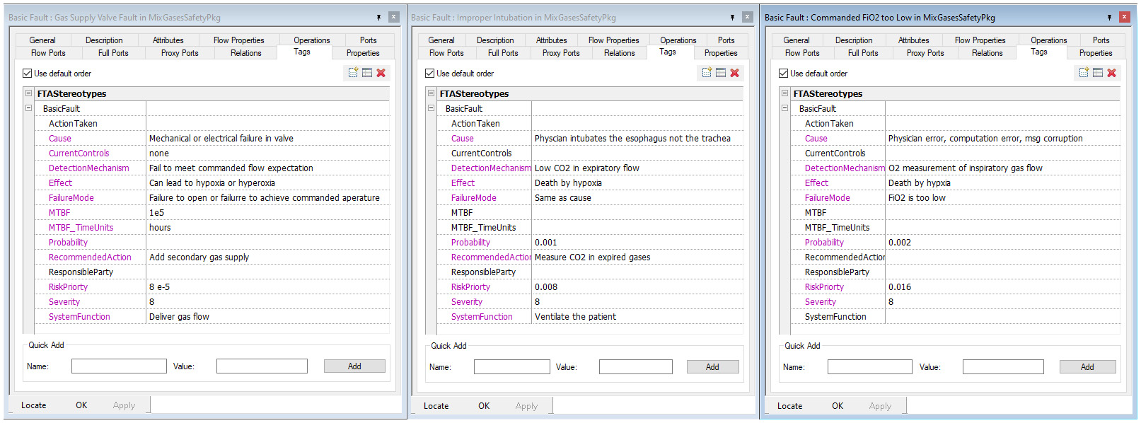
Figure 2.57 – Fault metadata
Create a causality model
Figure 2.58 shows the initial FTA. This FTA doesn't include any safety mechanisms, which will be added shortly. Nevertheless, this FTA shows a causality tree linking the faults to the hazard with a combination of logic operators and logic flows:
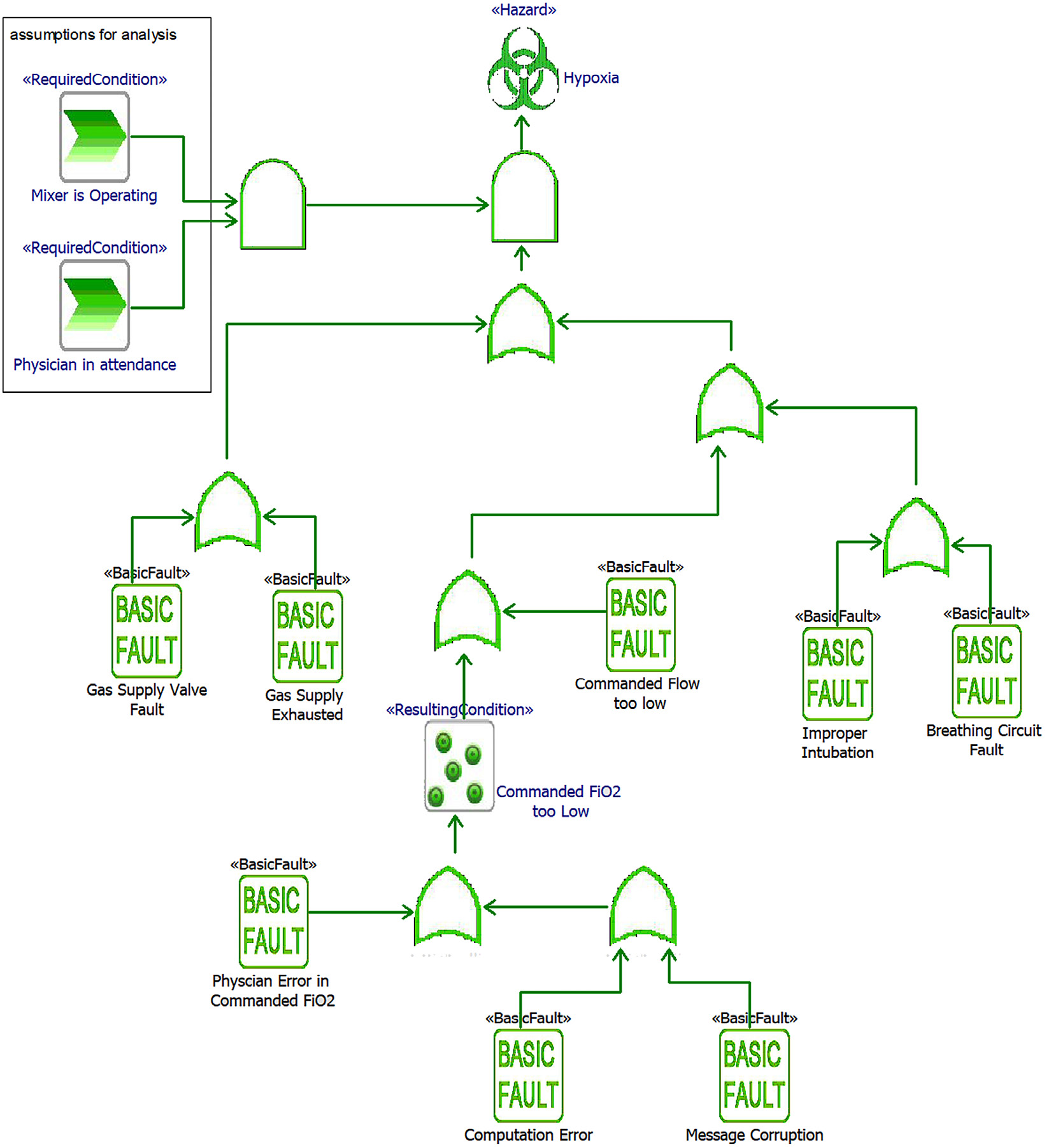
Figure 2.58 – Initial FTA
Identify cut sets
There are 10 primitive fault elements, so there are potentially 210 (1,024) cuts in the cut set, although we are only considering cases in which the assumptions are true, so that immediately reduces the set to 28 (256) possibilities. All of these are ORed together so it is enough to independently examine just the 8 basic faults.
Add safety measures
Adding a safety measure reduces either the likelihood or the severity of the outcome of a fault to an acceptable level. This is done on the FTA by creating anding-redundancy. This means that for the fault to have its original effect both the original fault must occur and the safety measure must fail. The likelihood of both failing is the product of their probabilities. For example, if the Gas Supply Valve Fault has a probability of 8 x 10⁻⁵ and we add a safety measure of a gas supply backup that automatically kicks in that has a probability of failure of 2 x 10⁻⁶, then the resulting probability of both failing is 16 x 10-11. Acceptable probabilities of hazards can be determined from the safety standard being used.
For the identified faults, we will add the following safety measures:
- Gas Supply Valve Fault safety measure: Secondary Gas Supply
- Gas Supply Exhausted fault safety measure: Secondary Gas Supply
- Improper Intubation fault safety measures: CO2 Sensor on Expiratory Flow and Alarm On Fault
- Breathing Circuit Fault safety measures: Inspiratory Limb Flow Sensor and Alarm On Fault
- Physician Error In Commanded O2 safety measures: Range Check Commanded O2 and Alarm On Fault
- Computation Error fault safety measures: Secondary Parallel Computation and Alarm On Fault
- Message Corruption fault safety measure: Message CRC
- Commanded Flow Too Low fault safety measures: Inspiratory Limb Flow Sensor and Alarm On Fault
Adding these results in a more detailed FTA. To ensure readability, transfer operators are added to break up the diagram by adding a sub-diagram for Commanded FiO2 Too Low. Figure 2.59 shows the high-level FTA diagram with safety measures added. Note that they are added in terms of what happens when they fail. Failure of safety measures is indicated with a red bold font for emphasis.
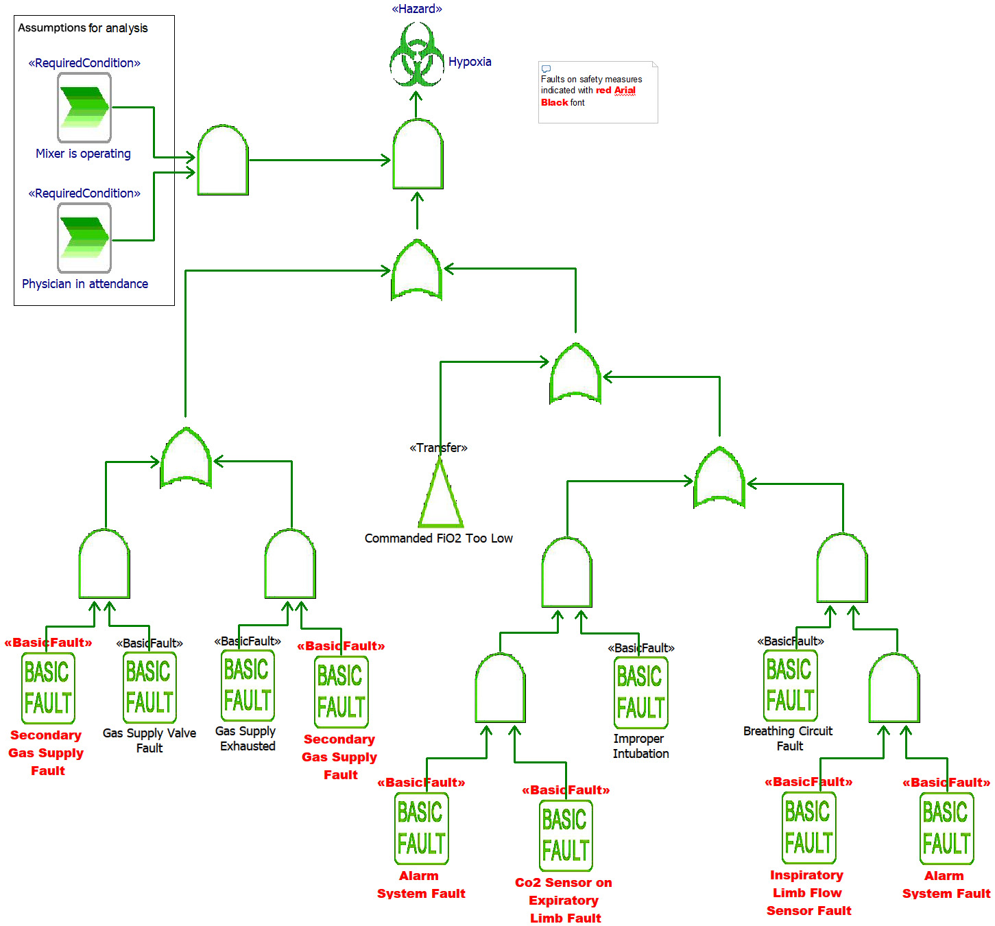
Figure 2.59 – Elaborated FTA diagram
Note also the use of the transfer operator to connect this diagram with the more detailed one for the sub-diagram shown in Figure 2.60:
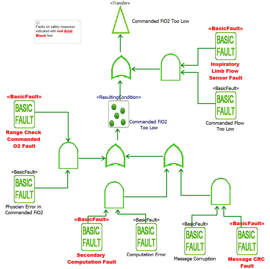
Figure 2.60 – Commanded FIO2 flow Too Low FTA
Review the safety concept
The set of safety measures addresses all the identified safety concerns.
Add safety requirements
Now that we have identified the safety measures necessary to develop a safe system, we must create the requirements that mandate their inclusion. These are shown in Figure 2.61:
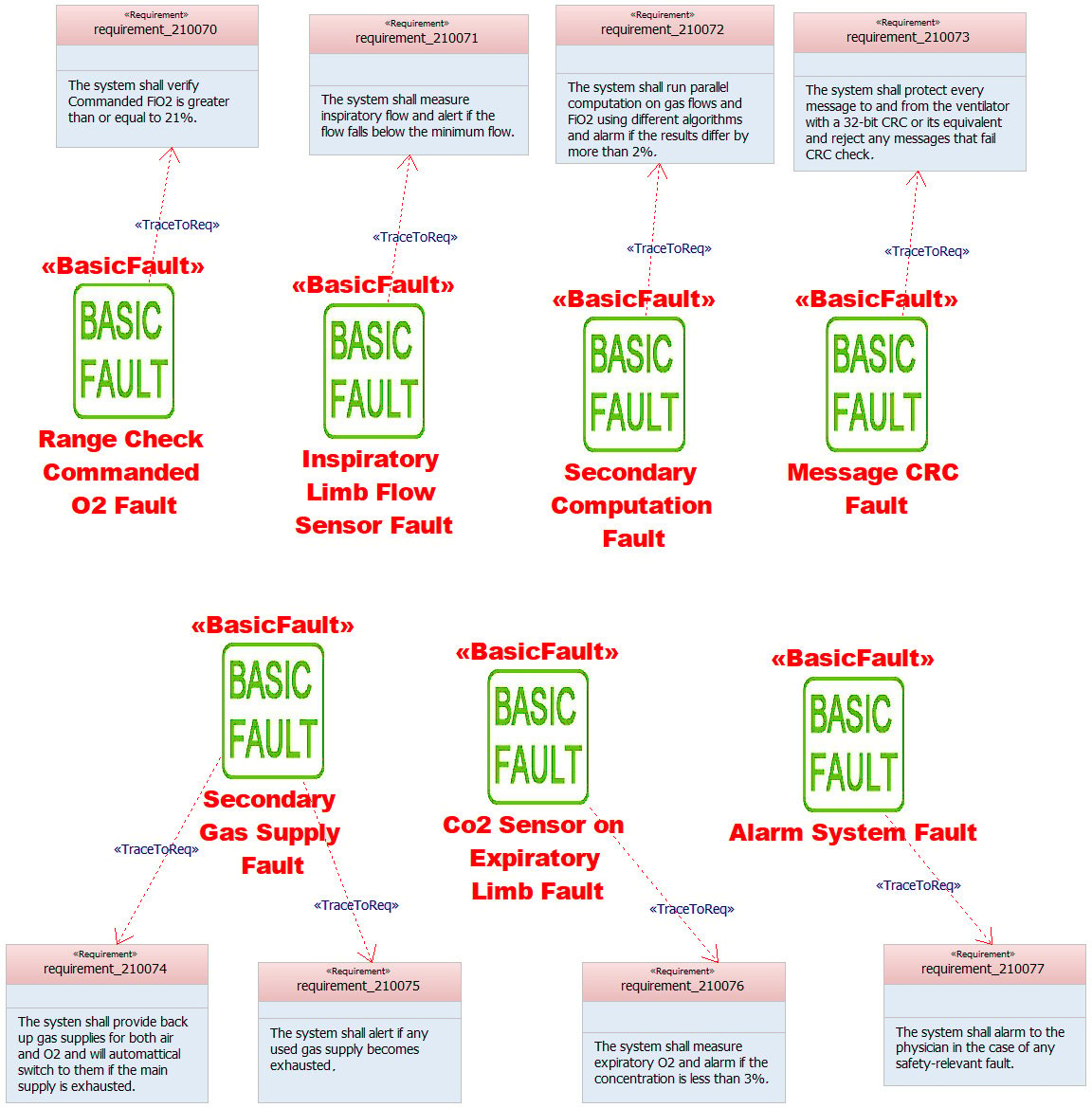
Figure 2.61 – Safety requirements


