Doing math with GLM
Every 3D graphics application needs some sort of math utility functions, such as basic linear algebra or computational geometry. This book uses the OpenGL Mathematics (GLM) header-only C++ mathematics library for graphics, which is based on the GLSL specification. The official documentation (https://glm.g-truc.net) describes GLM as follows:
Getting ready
Get the latest version of GLM using the Bootstrap script. We use version 0.9.9.8:
{
  "name": "glm",
  "source": {
    "type": "git",
    "url": "https://github.com/g-truc/glm.git",
    "revision": "0.9.9.8"
  }
}
Let's make use of some linear algebra and create a more complicated 3D graphics example. There are no lonely triangles this time. The full source code for this recipe can be found in Chapter2/02_GLM.
How to do it...
Let's augment the example from the previous recipe using a simple animation and a 3D cube. The model and projection matrices can be calculated inside the main loop based on the window aspect ratio, as follows:
- To rotate the cube, the model matrix is calculated as a rotation around the diagonal
(1, 1, 1)axis, and the angle of rotation is based on the current system time returned byglfwGetTime():const float ratio = width / (float)height; const mat4 m = glm::rotate( glm::translate(mat4(1.0f), vec3(0.0f, 0.0f, -3.5f)), (float)glfwGetTime(), vec3(1.0f, 1.0f, 1.0f)); const mat4 p = glm::perspective( 45.0f, ratio, 0.1f, 1000.0f);
- Now we should pass the matrices into shaders. We use a uniform buffer to do that. First, we need to declare a C++ structure to hold our data:
struct PerFrameData {
  mat4 mvp;
  int isWireframe;
};
The first field,
mvp, will store the premultiplied model-view-projection matrix. TheisWireframefield will be used to set the color of the wireframe rendering to make the example more interesting. - The buffer object to hold the data can be allocated as follows. We use the Direct-State-Access (DSA) functions from OpenGL 4.6 instead of the classic bind-to-edit approach:
const GLsizeiptr kBufferSize = sizeof(PerFrameData);
GLuint perFrameDataBuf;
glCreateBuffers(1, &perFrameDataBuf);
glNamedBufferStorage(perFrameDataBuf, kBufferSize,  nullptr, GL_DYNAMIC_STORAGE_BIT);
glBindBufferRange(GL_UNIFORM_BUFFER, 0,  perFrameDataBuf, 0, kBufferSize);
The
GL_DYNAMIC_STORAGE_BITparameter tells the OpenGL implementation that the content of the data store might be updated after creation through calls toglBufferSubData(). TheglBindBufferRange()function binds a range within a buffer object to an indexed buffer target. The buffer is bound to the indexed target of0. This value should be used in the shader code to read data from the buffer. - In this recipe, we are going to render a 3D cube, so a depth test is required to render the image correctly. Before we jump into the shaders' code and our main loop, we need to enable the depth test and set the polygon offset parameters:
glEnable(GL_DEPTH_TEST);
glEnable(GL_POLYGON_OFFSET_LINE);
glPolygonOffset(-1.0f, -1.0f);
Polygon offset is needed to render a wireframe image of the cube on top of the solid image without Z-fighting. The values of
-1.0will move the wireframe rendering slightly toward the camera.
Let's write the GLSL shaders that are needed for this recipe:
- The vertex shader for this recipe will generate cube vertices in a procedural way. This is similar to what we did in the previous triangle recipe. Notice how the
PerFrameDatainput structure in the following vertex shader reflects thePerFrameDatastructure in the C++ code that was written earlier:static const char* shaderCodeVertex = R"( #version 460 core layout(std140, binding = 0) uniform PerFrameData { uniform mat4 MVP; uniform int isWireframe; }; layout (location=0) out vec3 color; - The positions and colors of cube vertices should be stored in two arrays. We do not use normal vectors here, which means we can perfectly share
8vertices among all the6adjacent faces of the cube:const vec3 pos[8] = vec3[8]( vec3(-1.0,-1.0, 1.0), vec3( 1.0,-1.0, 1.0), vec3(1.0, 1.0, 1.0), vec3(-1.0, 1.0, 1.0), vec3(-1.0,-1.0,-1.0), vec3(1.0,-1.0,-1.0), vec3( 1.0, 1.0,-1.0), vec3(-1.0, 1.0,-1.0) ); const vec3 col[8] = vec3[8]( vec3(1.0, 0.0, 0.0), vec3(0.0, 1.0, 0.0), vec3(0.0, 0.0, 1.0), vec3(1.0, 1.0, 0.0), vec3(1.0, 1.0, 0.0), vec3(0.0, 0.0, 1.0), vec3(0.0, 1.0, 0.0), vec3(1.0, 0.0, 0.0) );
- Let's use indices to construct the actual cube faces. Each face consists of two triangles:
const int indices[36] = int[36](
  // front   0, 1, 2, 2, 3, 0,
  // right   1, 5, 6, 6, 2, 1,
  // back   7, 6, 5, 5, 4, 7,
  // left   4, 0, 3, 3, 7, 4,
  // bottom   4, 5, 1, 1, 0, 4,
  // top   3, 2, 6, 6, 7, 3
);
- The
main()function of the vertex shader looks similar to the following code block. Thegl_VertexIDinput variable is used to retrieve an index fromindices[], which is used to get corresponding values for the position and color. If we are rendering a wireframe pass, set the vertex color to black:void main() { int idx = indices[gl_VertexID]; gl_Position = MVP * vec4(pos[idx], 1.0); color = isWireframe > 0 ? vec3(0.0) : col[idx]; } )"; - The fragment shader is trivial and simply applies the interpolated color:
static const char* shaderCodeFragment = R"(
#version 460 core
layout (location=0) in vec3 color;
layout (location=0) out vec4 out_FragColor;
void main()
{
  out_FragColor = vec4(color, 1.0);
};
)";
The only thing we are missing now is how we update the uniform buffer and submit actual draw calls. We update the buffer twice per frame, that is, once per each draw call:
- First, we render the solid cube with the polygon mode set to
GL_FILL:PerFrameData perFrameData = { .mvp = p * m, .isWireframe = false }; glNamedBufferSubData( perFrameDataBuf, 0, kBufferSize, &perFrameData); glPolygonMode(GL_FRONT_AND_BACK, GL_FILL); glDrawArrays(GL_TRIANGLES, 0, 36); - Then, we update the buffer and render the wireframe cube using the
GL_LINEpolygon mode and the-1.0polygon offset that we set up earlier withglPolygonOffset():perFrameData.isWireframe = true; glNamedBufferSubData( perFrameDataBuf, 0, kBufferSize, &perFrameData); glPolygonMode(GL_FRONT_AND_BACK, GL_LINE); glDrawArrays(GL_TRIANGLES, 0, 36);
The resulting image should look similar to the following screenshot:
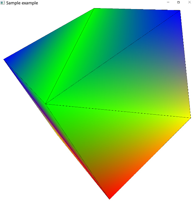
Figure 2.2 – The rotating 3D cube with wireframe contours
There's more...
As you might have noticed in the preceding code, the glBindBufferRange() function takes an offset into the buffer as one of its input parameters. That means we can make the buffer twice as large and store two different copies of PerFrameData in it. One with isWireframe set to true and another one set to false. Then, we can update the entire buffer with just one call to glNamedBufferSubData(), instead of updating the buffer twice, and use the offset parameter of glBindBufferRange() to feed the correct instance of PerFrameData into the shader. This is the correct and most attractive approach, too.
The reason we decided not to use it in this recipe is that the OpenGL implementation might impose alignment restrictions on the value of offset. For example, many implementations require offset to be a multiple of 256. Then, the actual required alignment can be queued as follows:
GLint alignment;
glGetIntegerv(  GL_UNIFORM_BUFFER_OFFSET_ALIGNMENT, &alignment);
The alignment requirement would make the simple and straightforward code of this recipe more complicated and difficult to follow without providing any meaningful performance improvements. In more complicated real-world use cases, particularly as the number of different values in the buffer goes up, this approach becomes more useful.