
Wiring up the robot
With the robot built and the electronic components attached, it is time to wire it up! The importance of good wiring of a robot is an often-overlooked part of a robot build, but it is critical to your robot’s reliability. Figure 12.6 gives you an overview of the complete wiring that we will discuss in detail in the following paragraphs:
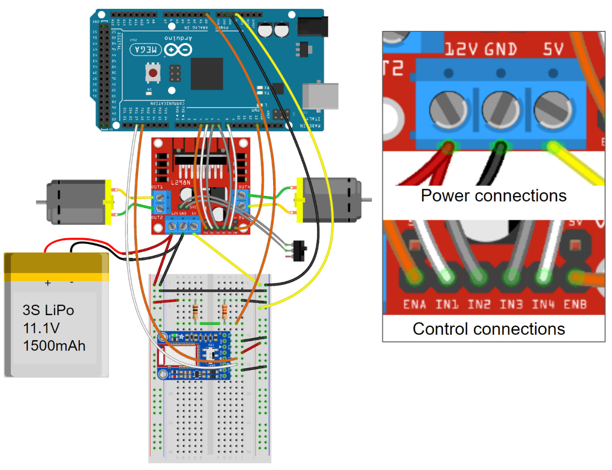
Figure 12.6 – Symbolic wiring diagram of the line-following robot with close-ups of the motor driver connections
Let us split the aspects of wiring into three categories (battery and motor, connections on the breadboard, and connections between boards) and go over these three categories one by one.
Battery and motor connections
Most hobby lithium batteries come with high-current connectors, such as the red Deans connectors (also called T-connectors), or the yellow XT60 connectors. These connectors are designed to carry high currents and ensure correct polarity when you mate them. You will need to buy or make a mating pigtail connector cable that you can use to connect the battery to the motor controller board. It is a very good idea to integrate a 5A fuse into this cable, especially if you use lithium batteries. You can connect the pigtail to the motor controller via the screw terminals on the board, which makes for a secure and safe connection. Just make sure that there are no stray copper strands coming from your cable that could potentially cause a short circuit between the battery poles (you can tin the cable ends with a soldering iron or use crimp-on ferrules to eliminate this risk). Also, double-check that the polarity is correct. Because the cables from the batteries carry the most current anywhere in your robot, you will want to use thick cable stock for this connection. Soldering thick cables to high-current connectors requires a strong soldering iron that can deliver the required heat quickly. If your soldering iron is not strong enough and takes a long time to heat up the cable and connectors, you might damage both and end up with an unreliable solder joint.
Most L298N motor driver boards have screw terminals for the motor connections as well. Attach cables to your motors with the included connectors or by soldering directly to the motor terminals. If your motor has an encoder and the motor and encoder cables all exit in one bundle, consult the datasheet to identify the two motor cables. Connect them to the two outputs of the motor driver shield via the screw terminals. Since we do not use the motor encoders for this project, you can just stow them somewhere – for example, by routing them along the frame of your robot and securing them with clear tape.
On-breadboard connections
So far, we always used flexible jumper cables to connect our Arduino board to other parts of our project. There is a better solution for connections between components and rails on a breadboard, namely, rigid jumper wires. You can buy them in sets of different lengths and colors. They are the best choice for on-breadboard connections because they keep the board much more organized than long, flexible cables. For this robot, you can use these wires to connect the two ground rails along the outer edges of the breadboard and to connect the Bluefruit BLE adapter to power. You can also use this type of wire to make the connections between the GND, 5V, and battery voltage terminals of the motor controller and the respective power rails of the breadboard, just to keep the wiring as organized as possible.
Inter-board connections
For the connections between the three boards, we can use the same flexible jumper cables that we have been using in the previous experiments. None of these connections carry significant currents, so thin jumpers are sufficient. Battery power, GND, and 5V need to be routed from the motor controller to the breadboard where we use one of the power rails for the battery voltage and the other for 5V. From there, 5V and GND are connected to the Arduino board. We also connect the Arduino’s Serial2 port to the Bluefruit BLE adapter on the breadboard (remember to cross TX and RX) and the Arduino’s A0 analog input to the center point of the battery voltage divider. Lastly, three signals per motor need to be connected from the Arduino to the motor controller: one for enable input (PWM) and two for the direction inputs.
Note
It is important to ensure that the GND inputs of all components of the robot are connected to one another. Otherwise, potentially confusing and unexpected behavior can occur.
The following is a photo of how the robot looks when it is fully wired up:
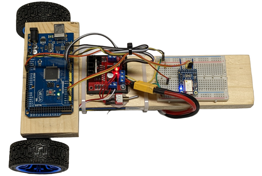
Figure 12.7 – Wired up and ready for a test drive
If you build the robot with the bigger motors and wheels that we will be using for the next chapter’s self-balancing robot, it will look like this:
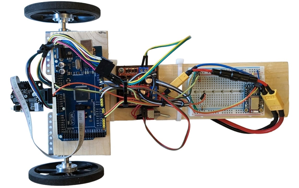
Figure 12.8 – The same robot, but with bigger motors and wheels (and with the camera attached)
With the wiring done, you have completed your first mobile robot platform, which you can now use as the base for a lot of exciting experiments. Congratulations!