Hemispheric ambient light
Ambient light is the easiest light model to implement and yet it is very important to the overall look of your scene. For the most part, ambient light refers to any light in the scene that cannot be directly tied to a specific light source. This definition is flexible and its implementation will be shown soon.
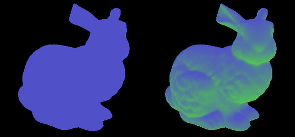
In the past, a single constant color value was used for every mesh in the scene that provides a very flat result. As programmable shaders became more available, programmers switched from constant color to other solutions that take the mesh normal into account and avoid the flat look. Hemispheric lighting is a very common method to implement ambient lighting that takes normal values into account and does not require a lot of computations. The following screenshot shows the same mesh rendered with a constant ambient color (left-hand side) and with hemispheric lighting (right-hand side):

As you can see, constant ambient light hides all the mesh detail, while hemispheric light provides a much more detailed result.
Getting ready
Hemispheric ambient light requires two colors that represent the light coming from above and below each mesh being rendered. We will be using a constant buffer to pass those colors to the pixel shader. Use the following values to fill a D3D11_BUFFER_DESC object:
|
Constant Buffer Descriptor Parameter |
Value |
|---|---|
|
|
|
|
|
|
|
|
|
|
|
|
The reset of the descriptor fields should be set to 0.
Creating the actual buffer, which is stored as a pointer to a ID3D11Buffer object, call the D3D device function CreateBuffer with the buffer-descriptor pointer as the first parameter, NULL as the second parameter, and a pointer to your ID3D11Buffer pointer as the last parameter.
How to do it...
All lighting calculations are going to be performed in the pixel shader. This book assumes that you have the basic knowledge to set up and issue the draw call for each mesh in the scene. The minimum calculation a vertex shader has to perform for each mesh is to transform the position into projected space and the normal into world space.
Note
If you are not familiar with the various spaces used in 3D graphics, you can find all the information you will need on Microsoft's MSDN at http://msdn.microsoft.com/en-us/library/windows/desktop/bb206269%28v=vs.85%29.aspx.
As a reference, the following vertex shader code can be used to handle those calculations:
cbuffer cbMeshTrans : register( b0 )
{
  float4x4  WorldViewProj  : packoffset( c0 );
  float4x4  World    : packoffset( c4 );
}

struct VS_INPUT
{
  float4 Pos  : POSITION;
  float3 Norm  : NORMAL;
  float2 UV  : TEXCOORD0;
};

struct VS_OUTPUT
{
  float4 Pos  : SV_POSITION;
  float2 UV  : TEXCOORD0;
  float3 Norm  : TEXCOORD1;
};

VS_OUTPUT RenderSceneVS(VS_INPUT IN)
{
  VS_OUTPUT Output;

  // Transform position from object to projection space
  Output.Pos = mul(IN.Pos, WorldViewProj);

  // Copy the texture coordinate through
  Output.UV = input.TextureUV;

  // Transform normal from object to world space
  Output.Norm = mul(IN.Norm, (float3x3)World);

  return Output;
}
Tip
Downloading the example code
You can download the example code files for all Packt books you have purchased from your account at http://www.packtpub.com. If you purchased this book elsewhere, you can visit http://www.packtpub.com/support and register to have the files e-mailed directly to you.
Again, this code is for reference, so feel free to change it in any way that suits your needs.
In the pixel shader, we will use the following deceleration to access the values stored in the constant buffer:
cbuffer HemiConstants : register( b0 )
{
  float3 AmbientDown   : packoffset( c0 );
  float3 AmbientRange  : packoffset( c1 );
}
Note
See the How it works... section for full details for choosing the values for these two constants.
Unless you choose to keep the two constant buffer values constant, you need to update the constant buffer with the values before rendering the scene. To update the constant buffer, use the context functions, Map and Unmap. Once the constant buffer is updated, bind it to the pixel shader using the context function PSSetConstantBuffers.
Our pixel shader will be using the following helper function to calculate the ambient value of a pixel with a given normal:
float3 CalcAmbient(float3 normal, float3 color)
{
  // Convert from [-1, 1] to [0, 1]
  float up = normal.y * 0.5 + 0.5;
  // Calculate the ambient value
  float3 Ambient = AmbientDown + up * AmbientUp;

  // Apply the ambient value to the color
  return Ambient * color;
}
This function assumes the normal y component is the up/down axis. If your coordinate system uses a different component as the vertical axis, change the code accordingly.
Similar to the vertex shader, the code for the pixel shader entry point depends on your specific mesh and requirements. As an example, the following code prepares the inputs and calls the helper function:
// Normalize the input normal
float3 normal = normalize(IN.norm);

// Convert the color to linear space
color = float4(color.rgb * color.rgb, color.a);

// Call the helper function and return the value
return CalcAmbient(normal, color);
How it works...
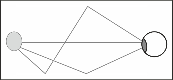
In order to understand how ambient light works, it is important to understand the difference between how light works in real life and the way it works in computer graphics. In real life, light gets emitted from different sources such as light bulbs and the Sun. Some of the rays travel straight from the source to our eyes, but most of them will hit surfaces and get reflected from them in a different direction and with a slightly different wave length depending on the surface material and color. We call each time the light gets reflected from a surface to a bounce. Since each light bounce changes the wave length, after a number of bounces the wave length is no longer visible; so what our eyes see is usually the light that came straight from the source plus the light that bounced for a very small amount of times. The following screenshot demonstrates a situation where a light source emits three rays, one that goes directly to the eye, one that bounces once before it reaches the eye, and one that bounces twice before it reaches the eye:

In computer graphics, light calculation is limited to light that actually reaches the viewer, which is usually referred to as the camera. Calculating the camera's incoming light is normally simplified to the first bounce mostly due to performance restrictions. Ambient light is a term that usually describes any light rays reaching the camera that bounced from a surface more than once. In the old days, when GPUs where not programmable, ambient light was represented by a fixed color for the entire scene.
Note
Graphics Processing Unit (GPU) is the electronic part in charge of graphics calculations. When a GPU is not programmable, we say that it uses a fixed pipeline. On the other hand, when a GPU is programmable, we say that it uses a programmable pipeline. DirectX 11-enabled cards are all programmable, so you are not likely to work with a fixed pipeline.
As the first screenshot in this recipe introduction showed, using a fixed color provides a flat and artificial look. As programmable GPUs became commonly available, developers finally had the flexibility to implement better the ambient light models that provide a more natural look. Although the hemispheric ambient light model is not a perfect representation of light that bounced more than once, it gained its popularity due to its simplicity and quality.
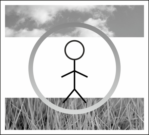
Hemispheric ambient light splits all light rays that affect the mesh getting rendered to those that arrived from above and below the mesh. Each one of these two directions is assigned a different color and intensity. To calculate the ambient light value of a given pixel, we use the normal vertical direction to linearly blend the two colors. As an example, in an outdoor scene with blue sky and grassy ground, the ambient light interpolates across the hemisphere, as shown in the following image:

Picking a pair of colors that properly represents the mesh surrounding for the upper and lower hemisphere is probably the most important step in this recipe. Though you can write code that picks the color pairs based on the scene and the camera position, in most games the values are handpicked by artists.
Note
Note that even though the color pairs are constant for all the pixels affected by the draw call, they don't have to be constant overtime or for all the meshes in the scene. In fact, changing the color values based on the time of day or room properties is a very common practice.
One thing to keep in mind when picking the colors is the space they are in. When an artist manually picks a color value, he usually comes up with color values in what is known as gamma space. Light calculations on the other hand should always be performed in linear space. Any color in gamma space can be converted to linear space by raising it to the power of 2.2, but a faster and common approximation is to square the color (raising it to the power of 2). As you can see in the pixel shader entry point, we converted the pixel color to linear space before passing it to the ambient calculation.
Tip
If you are not familiar with the gamma and linear color space, you should read about gamma correction to understand why it is so important to calculate lighting in linear space in the following link: http://www.slideshare.net/naughty_dog/lighting-shading-by-john-hable.
Once you picked the two values and converted them to linear space, you will need to store the colors in the constant buffer as the down color and the range to the upper color. In order to understand this step, we should look at the way the ambient color is calculated inside the helper function. Consider the following linear interpolation equation:
DownColor * (1-a) + UpColor * a = DownColor + a * (UpColor - DownColor)
The equation on the left-hand side blends the two colors based on the value, while the equation on the right-hand side does the exact same thing only with the down color and the range between the two colors. The GPU can handle the calculation on the right-hand side with a single instruction (this instruction is called madd), which makes it faster than the equation on the left-hand side. Since we use the equation on the left-hand side, you will need to store the upper, minus-lower color into the second constant buffer parameter.


