Using Grips efficiently
Using Grips in AutoCAD can speed up simple object editing without any command. First, let’s review the basic GRIP options for the common object types for those who don’t use Grips now.
Using Common Grip commands
Grips in AutoCAD provides access to common editing commands such as STRETCH, MOVE, ROTATE, MIRROR, and SCALE. Most users should know these simple GRIP functions, but just in case you don’t, let me demonstrate them quickly in the next exercise.
Using Common Grips
In this exercise, we will use Grips to do a simple COPY and ROTATE as an example:
- Open the
2-3_UsingGRIPS.dwgfile. - Using the In-Canvas View Controls, restore the Custom Model Views | 1-Basic Grips named view.
- Select the RECTANGLE object and notice the “blue” Grips that display at the ENDPOINT and MIDPOINT locations on the object.
- Select one of the corner Grips (blue square grip) and look at the Command Line.
- When selecting a grip, you are automatically placed in the Stretch command. Use the Spacebar to cycle to the next command, which is Move. Use the Cursor Badges to keep track of which command mode you are using.


Figure 2.17: Grips common commands
- Press the Spacebar again to cycle to the next command, which is Rotate.

- Press the Spacebar again to cycle to the next command, the Scale command.

- Press the Spacebar again to cycle to the next command, the Mirror command.
- Last, press the Spacebar again to cycle back to the first command, the Stretch command.
- Use the Esc key to cancel the command and to clear the selection set.
Standard practice is to cycle through the Stretch, Move, Rotate, Scale, and Mirror commands and back to Stretch again using the Spacebar. However, you can access them directly by entering their abbreviations, as shown here:
ST– Stretch
MO– Move
RO– Rotate
SC– Scale
MI– Mirror
Note
You can also access the GRIP commands using a right-click menu.
- Select the RECTANGLE object and select one of the corner Grips (blue square grip).
- By default, you are in the Stretch command. Key in
ROin the Command Line to skip immediately to the Rotate command. - Use the Esc key to cancel the command and to clear the selection set.
This is a quick shortcut that is handy to know.
Note
The COPY command is not a grip mode but can be selected as an option within any of the other GRIP commands.
Note
Try using the Ctrl key when using the GRIP command. For example, if you press Ctrl during the ROTATE COPY command, the angle is repeated from the previous ROTATE COPY. If you release the Ctrl key, the angle is free to copy at any angle.
Let’s give that a try in the next exercise:
- Continue using the
2-3_UsingGRIPS.dwgfile. - Select the SQUARE object and select any GRIP on the object.
- Use the Spacebar to toggle to the Move command and key in
Cto make the MOVE action a Move-Copy of the SQUARE object. - Drag the SQUARE object to the RIGHT, and key in the value of
1unit, and left-click to complete the Move-Copy. - While still in this command, hold down the Ctrl key and drag the SQUARE object to the RIGHT until it locks into the 1-unit distance.
- Left-click to accept the new Move-Copy. Release Ctrl when you no longer want to use the snap distance for additional copies.
Note
Try using this Ctrl key option for any of the common GRIP commands.
Performing simple modifications on AutoCAD objects using these common GRIP commands can save time and improve your overall editing process.
Now, let’s look at what else these Grips provide besides the common commands we just reviewed.
Using Multi-Functional OBJECT Grips
In the following exercises, we will learn to use additional GRIP commands often overlooked by users. To access these multi-functional grips, you must hover over a grip, not select or left-click on a grip.
Lines
First, let’s look at an example of using these multi-functional grips to STRETCH a line and maintain the existing angle of the line:
- Continue using the
2-3_UsingGRIPS.DWGfile. - Using the Status Bar, turn OFF the Dynamic Input setting
 for this first example.
 - Select the LINE object and review the grips (blue squares) at the ENDPOINT and MIDPOINT locations.
- Hover over either ENDPOINT grip (blue square) to display the multi-functional pop-up menu, which gives you access to the Stretch and Lengthen commands.
- Select the Lengthen command from the pop-up menu to extend the existing LINE without modifying the angle of the line.
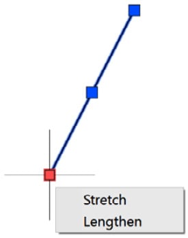
Figure 2.18: Lengthen Grip
- Left-click anywhere along the LINE object to define the length change and to complete the command.
- Using the Status Bar, turn ON the Dynamic Input setting
 for the next example.
 - Again, select the LINE object and hover over either ENDPOINT grip to access the Stretch and Lengthen commands. Note the additional dynamic dimensions available to visually control the length modification.
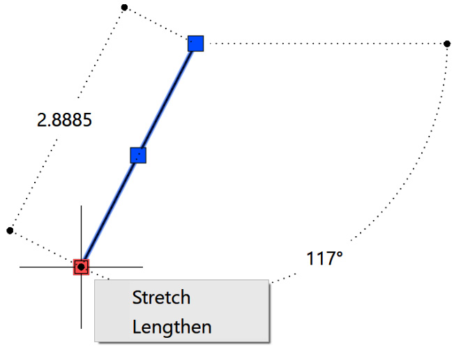
Figure 2.19: Lengthen Grip with Dynamic Input
Polylines
Next, let’s look at how to modify a POLYLINE object and quickly insert a new vertex using a multi-functional grip rather than an individual AutoCAD command:
- Continue using the
2-3_UsingGRIPS.DWGfile. - Select the RECTANGLE polyline object and hover over any corner grip (blue square) to access the multi-functional pop-up menu for the Stretch, Add Vertex, and Remove Vertex commands.
- Select the Add Vertex command from the pop-up menu to add a new vertex to the “next” edge of the rectangle. The new vertex is added between the “hover” grip and the next grip in the existing object’s vertices.

Figure 2.20: Add Vertex Grip
- Left-click in the view window to add another vertex to this POLYLINE shape. This is much easier than using the Pedit command to add a vertex, isn’t it?
- Use the Esc key on the keyboard to cancel all commands and clear all grips.
Utilizing these “hover” grip commands can provide greater flexibility and efficiency compared to using the identical command options available in each individual AutoCAD command.
Try out the following object GRIP options for these object types.
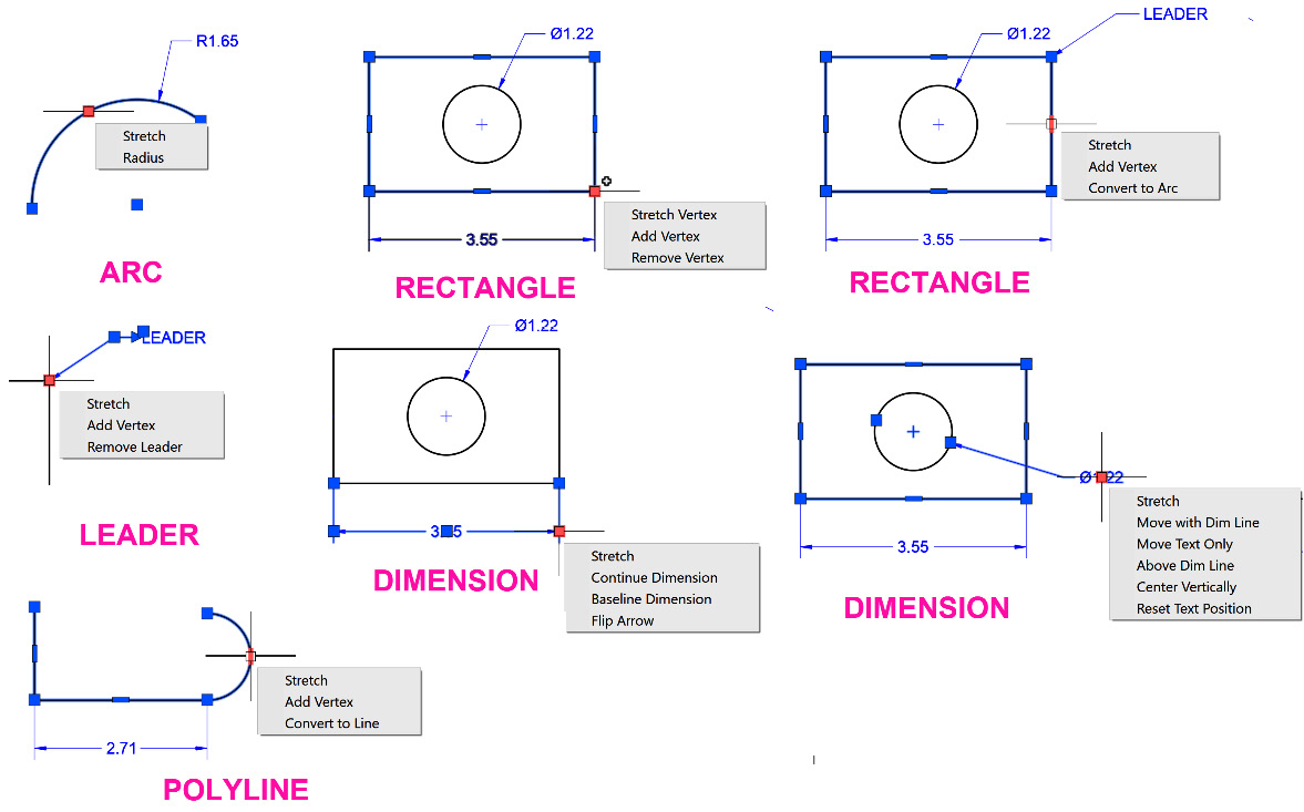
Figure 2.21: Additional GRIP commands
Selecting multiple GRIPS
When using grips, you can also select multiple grips on an object to better control the grip editing:
- Continue using the
2-3_UsingGRIPS.DWGfile. - Select the RECTANGLE polyline object and use the Shift key to select two corner grips.
- When both grips are selected (red squares), select either grip to edit the rectangle. With multiple grips selected, you lock their relationship to each other, allowing you to edit the RECTANGLE object differently.
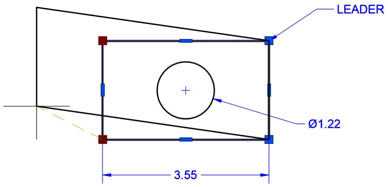
Figure 2.22: Select Multiple Grips
Customize the GRIP appearance
Last, let’s look at how you can customize the appearance of GRIPS in your AutoCAD.
Grip size
- Continue using the
2-3_UsingGRIPS.DWGfile. - Right-click anywhere in the view window and select the Options command.
- Using the Options dialog, select the Selection tab.
- Using the Grip Size slider bar, adjust the size of your grips as needed. The default size is 5. You can also use the following system variable to control the grip size.
|
GRIPSIZE |
|
|
Sets the size of the grip box, in device independent pixels. Type: Integer Saved in: Registry |
|
|
1-255 |
Defines the size of the GRIP icon. |
|
5 (default) |
|
I would like to modify the color of my grips to make them stand out better against the default dark color scheme and background.
Grip colors
Modify the colors of your grips to suit your view background color and the commonly used colors in your CAD standards:
- Continue using the file
2-3_Using GRIPS.DWG. - Right-click anywhere in the view window and select the Options command.
- Using the Options dialog, select the Selection tab.
- Select the Grip Colors button and using the Grip Colors dialog, modify the colors to your personal preference.
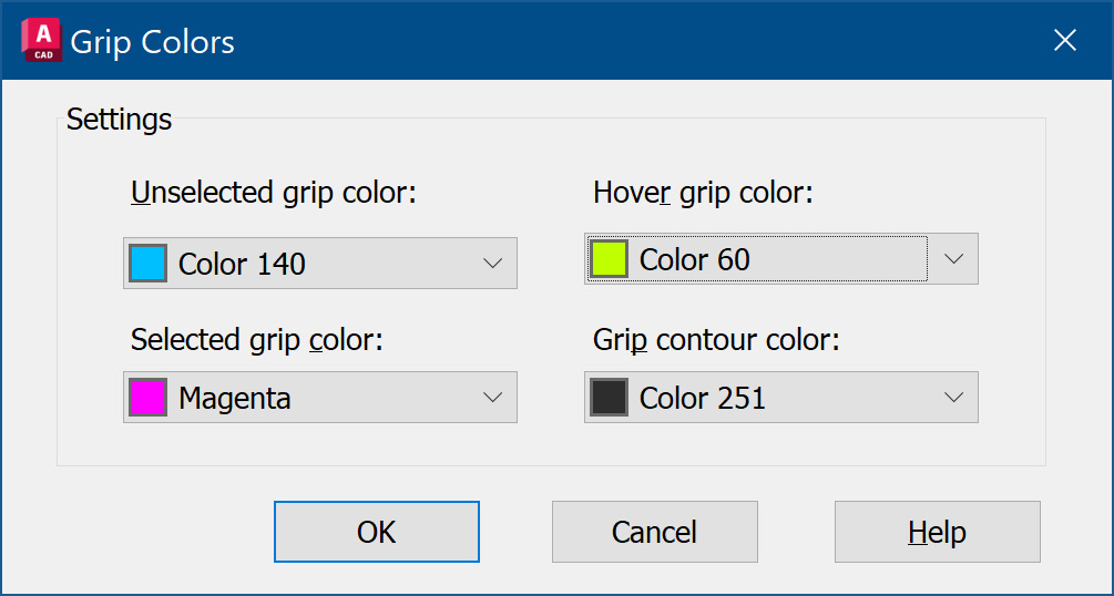
Figure 2.23: Grip colors
- Click OK to save the changes and click OK again to close the Options dialog.
As with other GRIP settings, the GRIP colors can be defined using the following system variables:
|
GRIPCOLOR |
|
|
Controls the color of unselected grips. The valid range is 1 to 255. Type: Integer Saved in: Registry |
|
|
1-255 |
Defines the unselected GRIP color. |
|
150 (default) |
|
|
GRIPHOVER |
|
|
Controls the fill color of an unselected grip when the cursor pauses over it. The valid range is 1 to 255. Type: Integer Saved in: Registry |
|
|
1-255 |
Defines the hover GRIP color. |
|
150 (default) |
|
|
GRIPHOT |
|
|
Controls the color of selected grips. The valid range is 1 to 255. Type: Integer Saved in: Registry |
|
|
1-255 |
Defines the selected GRIP color. |
|
12 (default) |
|
|
GRIPCONTOUR |
|
|
Controls the color of the grip outline. The valid range is 1 to 255. Type: Integer Saved in: Registry |
|
|
1-255 |
Defines the grip outline color. |
|
251 (default) |
|
Grip display settings
The remaining GRIP options include the ability to disable the use of Grips altogether:
|
GRIPS |
|
|
Controls the display of grips on selected objects. Type: Integer Saved in: Registry |
|
|
0 |
Hides grip display. |
|
1 |
Displays grips |
|
2 (default) |
Displays additional midpoint grips on polyline segments. |
Show Grips in blocks
Many times, displaying GRIPS for all objects in a block can be overwhelming. Using this setting, you can control whether the GRIPS displayed for block objects display only the block INSERTION location or all grips for the objects in the block.
Grip display limit
You can control how many grips are displayed in a multiple object selection set by defining the Object Selection Limit for display of grips setting, as shown in the following image. By default, AutoCAD will not display more than 100 grips in a selection set:
- Continue using the
2-3_UsingGRIPS.dwgfile. - Using the In-Canvas View Controls, restore the Custom Model Views | 1-Grip Limits named view.
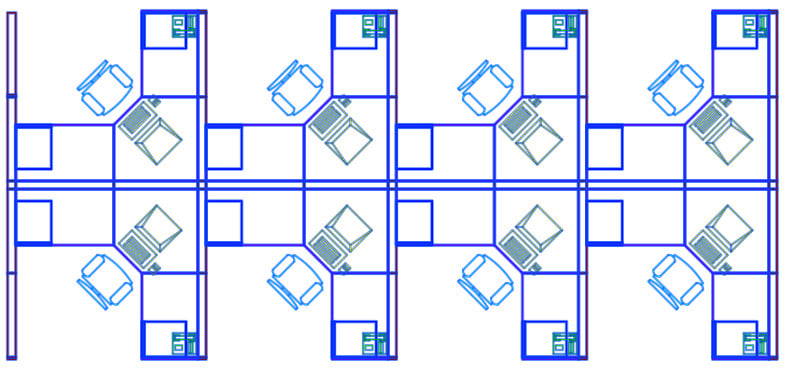
Figure 2.24: Grips limit 100
- Right-click anywhere in the view window and select the Options command.
- Using the Options dialog, select the Selection tab.
- Using the Grips section of the tab, locate the Object selection limit for display of grips setting and modify the value to
200. - Click the OK button to close the dialog.
- Select several objects again and review the changes to this setting.
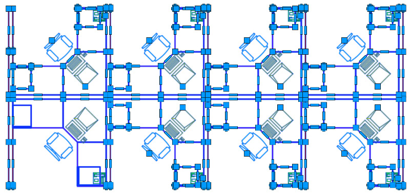
Figure 2.25: Grips limit 200
After completing this section, you can more fully utilize and customize your personal use of GRIPS in AutoCAD. Continue to explore what you can do with GRIPS to improve your editing efficiency.
Next, let’s learn how to use the GROUP commands for more than you have imagined.


