Creating the geodatabase
After we have designed the geodatabase schema, it is now time to author the geodatabase. In this section, we will use ArcCatalog to create the geodatabase. ArcCatalog is an application that allows us to author geodatabases, browse through them, add/delete datasets from geodatabases, and so on. To create your first geodatabase, perform the following steps:
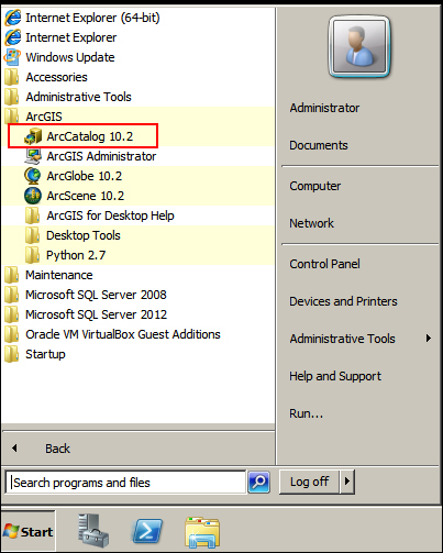
- Open ArcCatalog; you can find it in the Start menu under the ArcGIS folder, as explained in this chapter. The following screenshot illustrates this:
- Once you start the application, make sure you see the Catalog Tree window. This is the folder view of your computer, and this is where we will be doing most of the work.
- To show the Catalog Tree window, point the cursor to the Windows menu and then click on Catalog Tree.
- Next, you need to specify the folder where you will create your
Bestaurantsgeodatabase. - Using Windows Explorer, create a folder named
c:\gdb. This is where the geodatabase will go. - From the Catalog Tree window, right-click on the Folder Connections node and click on Connect to Folder…. This feature allows you to connect to your Windows folder.
- Browse to the new folder you just created,
c:\gdb, and then click on OK. - Select the folder and then right-click on the empty view to the right, point the cursor to New, then click on File Geodatabase, as shown in the following screenshot:
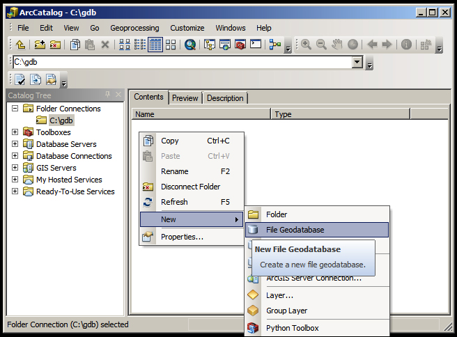
This will create a file geodatabase in the specified folder with a default name of New File Geodatabase.gdb; rename the new geodatabase to Bestaurants. The gdb extension is automatically appended.
Note
A file geodatabase is the proprietary geodatabase for Esri, structured as a folder with many files that can only be viewed and opened by Esri products or applications which support the file geodatabase API. This has an extension of gdb.
The spatial reference
Adding location information to a database requires two parameters, the actual location coordinates and how these coordinates are supposed to be drawn, which is also known as the spatial reference. The spatial reference describes whether the location is projected on a two- or three-dimensional map, and whether it should be defined for every dataset in the geodatabase that has a spatial component. While working in ArcMap, all datasets should share the same spatial reference.
Note
A spatial reference is a collection of properties that describe the system to locate a particular object in a coordinate system. You can find more information about this topic at http://bit.ly/lag_spatialreference.
There are a lot of spatial references tailored for different locations on the Earth. There are some standard references used universally, and among them is the WGS 84, which we will be continuously using in this book.
Creating the feature classes
In the previous section, we designed the logical schema for our geodatabase. We will now create the actual datasets, or the physical schema. First, we start by creating the feature classes as follows:
- Open ArcCatalog and browse to your
Bestaurantsgeodatabase in the Catalog Tree window. - Click on the
Bestaurantsfile geodatabase, right-click on the empty right panel, point the cursor to New, and then click on Feature Class…, as shown in the following screenshot: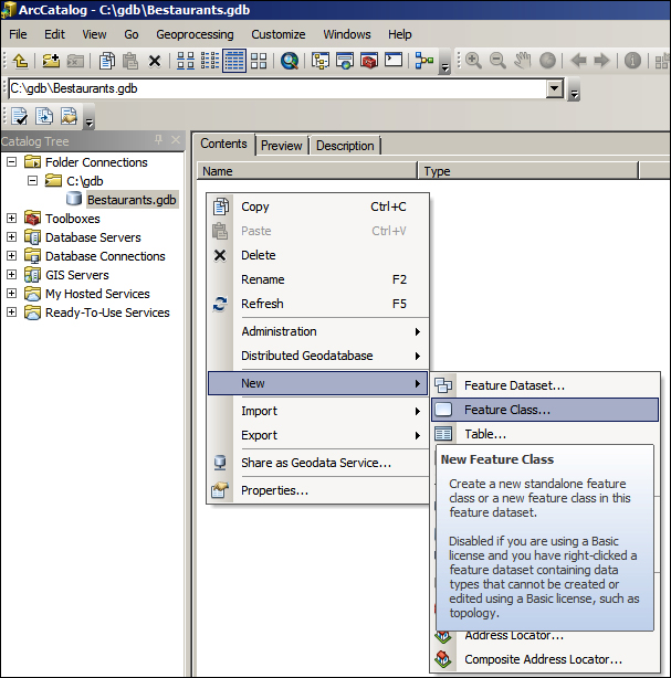
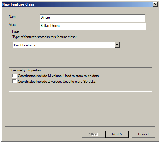
This will open up the New Feature Class dialog where you specify the basic properties of the feature class. In the Name field, type
Diners. This is the physical name of the feature class in the geodatabase, and it should not contain special characters and should not include any spaces. - Type
Belize Dinersin the Alias field. This is a description of the feature class's name. It can be anything you want. When you add a new layer, it takes this alias name by default. - In the Type drop-down list, select Point Features to create the feature class with point geometry.
The Geometry Properties section offers advanced options to enable the feature class. This includes the M value that helps in the route information for linear features and the Z value that is used for 3D representation, which enables the elevation and extrusion of features. The Z value can be useful, for example, if a restaurant is located on the 11th floor of the Ritz Carlton hotel.
Note
Besides X and Y coordinates, the M value can be added to each vertex on a line to provide more information, such as the direction.
Unlike X and Y coordinates, the Z value can be considered as the height of a feature upward or downwards. This value can be assigned to features so they are represented in a 3D plane.
- Since we don't need to store route or 3D data at this stage, leave the M and Z values unchecked. Click on Next. This is illustrated in the following screenshot:
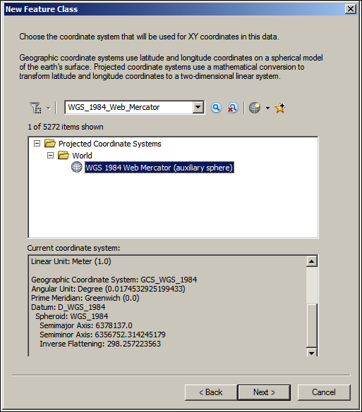
In the next dialog box, you will set the spatial reference for our new feature class. You will use the WGS_1984_Web_Mercator standard spatial reference, which is also used by Google Maps.
- In the spatial reference drop-down list, select WGS_1984_Web_Mercator and press Enter to find its item.
- Expand the Projected Coordinate Systems node, then expand the World node, and then click on the WGS 1984 Web_Mercator (auxiliary sphere) node, as illustrated in the following screenshot.
- Click on Next to move to the next form.
Next, we set the XY Tolerance value for the feature class. As you start adding features, you might want to add some features close to each other, but you don't want them to snap into the same position. In this case, make this value smaller to get a higher accuracy for each feature position. However, sometimes, you will need to add features on top of each other, making them overlap on purpose, especially if you have Z values. Too small a tolerance value might make it difficult to snap these features into a single location and might cause problems with shared boundaries.
- As you can see, this value needs to be carefully planned, but for now, leave the XY Tolerance value to its default value, which is
0.001meters, and click on Next.Note
The XY Tolerance value is the minimum distance after which two features will snap together.
In the next form, we select the configuration keyword; choose the Default configuration keyword and click on Next.
Note
The configuration keyword is a table space in which feature classes and tables are stored. Each configuration has certain properties, such as the geometry type and file size, which are shared by all objects in that keyword.
Finally, we add the fields for our feature class. Note that two fields are already added for you. The first field is OBJECTID, which is also the primary key; a sequence number that represents each feature in the feature class uniquely.
Note
The primary key is a column by which a record is uniquely identified in a table or a dataset.
The second field is SHAPE, which if you remember, we have added by specifying the geometry type. So, we need to add three more fields: NAME, WEBSITE, and RATING; click on an empty row in the Field Name column and add the following fields:
|
Name |
Data Type |
|---|---|
|
NAME |
Text |
|
WEBSITE |
Text |
|
RATING |
Short Integer |
After adding all the fields, your dialog box should look like the following screenshot; click on Finish to create the feature class:

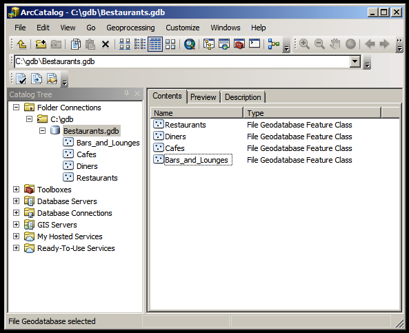
You just created your first feature class; if you take a look at the icon, you will see three small dots, which indicates that this feature class has a point geometry.
Using the same approach, create the rest of the feature classes, Cafes, Restaurants, and Bars_and_Lounges, in your geodatabase based on the schema we designed earlier.
Note
If you are creating multiple feature classes with similar fields, use the Import... feature in the fields' page to import the fields from an existing feature class. This could prove efficient when you are authoring your geodatabase.
After creating all the feature classes, your final geodatabase should look like the following screenshot:
