Powering up the Micro:bit
There are a few ways we can power up the Micro:bit. Let’s see them all one by one. The following diagram clearly shows the micro-USB port and the battery socket. We can power up the BBC Micro:bit using these:
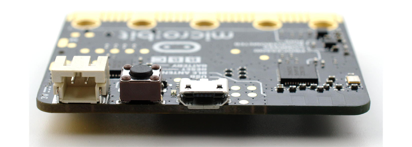
Figure 1.4 – The battery socket and micro-USB port (courtesy: https://commons.wikimedia.org/wiki/File:BBC_micro_bit_%2826238853955%29.png)
We can use a micro-USB male to USB male cable to power the Micro:bit. The following is the micro-USB end of such a cable:
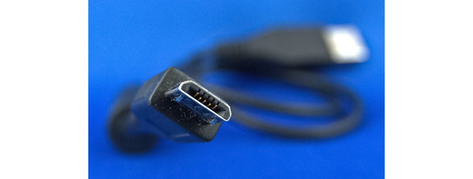
Figure 1.5 – A micro-USB male connector (courtesy: https://commons.wikimedia.org/wiki/File:MicroB_USB_Plug.jpg)
Insert this end into the Micro:bit, as shown in the following photo:
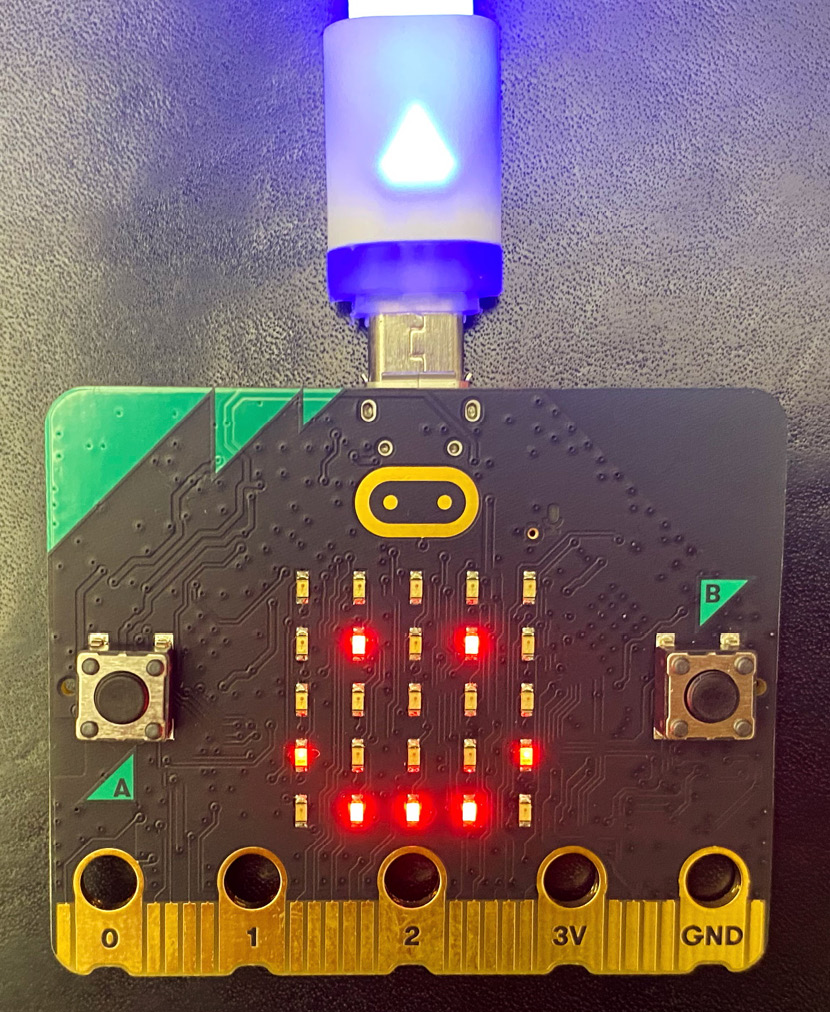
Figure 1.6 – A micro-USB male connector (courtesy: https://commons.wikimedia.org/wiki/File:Bbc-microbit-2021.jpg)
Insert the other end into a computer or a power bank. The following is an image of a mobile/portable power bank:
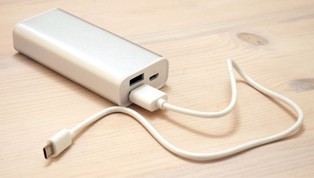
Figure 1.7 – A power bank with a micro USB cable attached (courtesy: https://commons.wikimedia.org/wiki/File:Portable_power_bank.jpg)
We can also use a pair of AAA batteries with a special connector, as shown in the following photo:
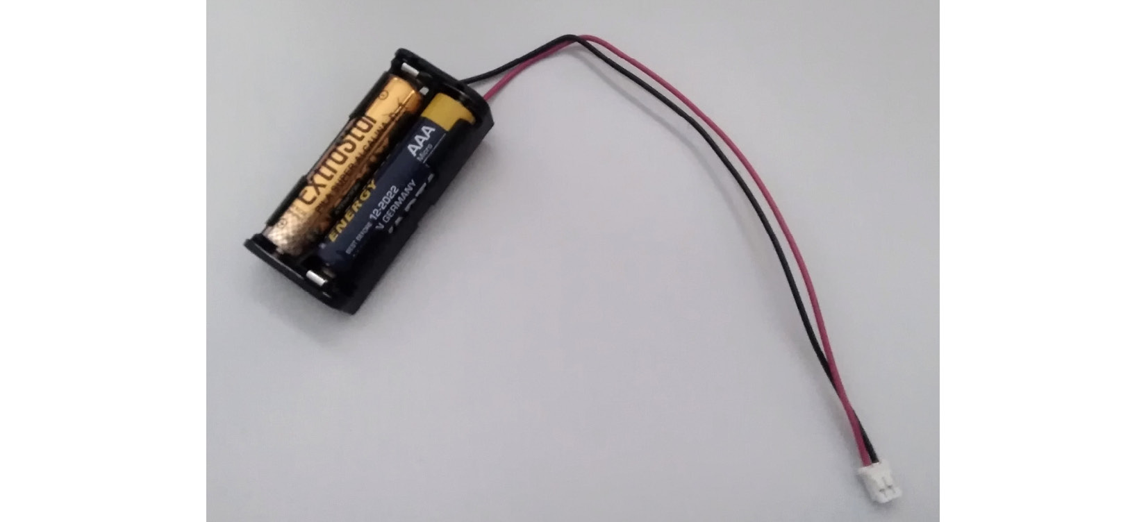
Figure 1.8 – A battery connector (courtesy: https://commons.wikimedia.org/wiki/File:Cavo_Microbit.jpg)
You can procure such a connector online at various marketplaces. One such page is https://www.sparkfun.com/products/15101. There are many other websites too that sell these connectors. You can also check your local makers’ electronic supply shops for this.
The following photo shows the Micro:bit powered up with this connector and a pair of AAA batteries:
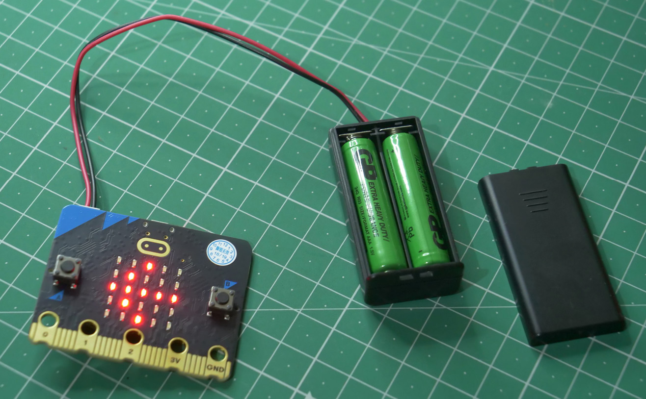
Figure 1.9 – A battery connector connected to the Micro:bit
We can also power the Micro:bit with a CR2032-type power cell, as shown in the following figure:

Figure 1.10 – CR2032 power cells (courtesy: https://commons.wikimedia.org/wiki/File:Cr2032-7mmgrid.jpg)
We can use various special connectors to connect it with the Micro:bit. One special connector board is MI – the power board by Kitronik (https://kitronik.co.uk/products/5610-mipower-board-for-the-bbc-microbit). Figure 1.11 shows a photo of the board, the nuts, and the CR2032 battery that comes with it:
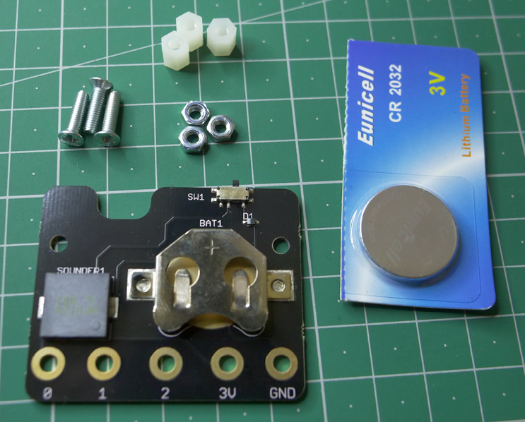
Figure 1.11 – The MI:power board and contents of the package
Figure 1.12 is a photo of the rear of the Micro:bit attached to the MI:power board:
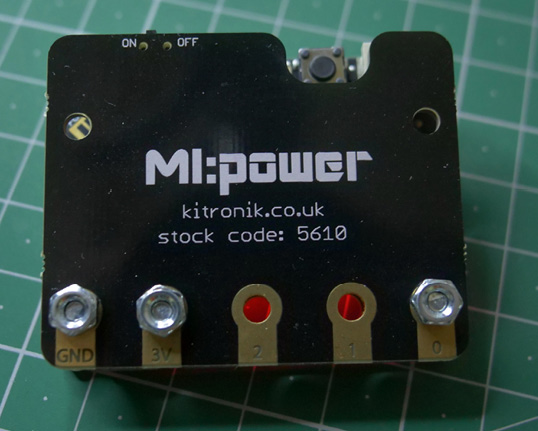
Figure 1.12 – The Micro:bit assembled with the MI:power board
We can see that there is a dedicated ON/OFF switch. Attaching the board to the Micro:bit is very easy, and we can check the instructions for assembly at https://kitronik.co.uk/products/5610-mipower-board-for-the-bbc-microbit.
Both versions of the Micro:bit come with booklets, as shown in the following image:
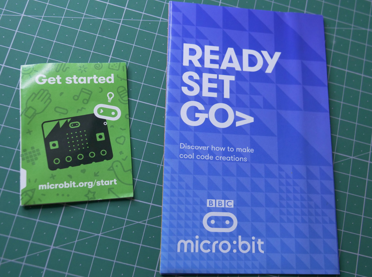
Figure 1.13 – Micro:bit instruction booklets
It is recommended to go through them for a better understanding.
The out-of-box experience
When we unbox the Micro:bit and power it up for the very first time, it runs a factory default program known as the out-of-box experience. It is lots of fun to learn about the features of the Micro:bit using this program. Unbox and power your Micro:bit to run this program. Enjoy exploring the features of the Micro:bit.
Now that we have explored various ways to power the Micro:bit, we will explore special hardware components known as breakout boards.