Search icon CANCEL
Subscription
0
Cart icon
Your Cart (0 item)
Close icon
You have no products in your basket yet
Save more on your purchases! discount-offer-chevron-icon
Savings automatically calculated. No voucher code required.
Arrow left icon
Explore Products
Best Sellers
New Releases
Books
Videos
Audiobooks
Learning Hub
Newsletter Hub
Free Learning
Arrow right icon
timer SALE ENDS IN
0 Days
:
00 Hours
:
00 Minutes
:
00 Seconds
Arrow up icon
GO TO TOP
Improving CAD Designs with Autodesk Fusion 360

You're reading from   Improving CAD Designs with Autodesk Fusion 360 A project-based guide to modelling effective parametric designs

Arrow left icon
Product type Paperback
Published in Sep 2023
Publisher Packt
ISBN-13 9781800564497
Length 596 pages
Edition 1st Edition
Arrow right icon
Author (1):
Arrow left icon
Kevin Michael Land Kevin Michael Land
Author Profile Icon Kevin Michael Land
Kevin Michael Land
Arrow right icon
View More author details
Toc

Table of Contents (22) Chapters Close

Preface 1. Part 1: Simple, Fun Projects for Around the Home
2. Chapter 1: Working within the Design Workspace FREE CHAPTER 3. Chapter 2: Planes, Sketches, Constraints, and Parametric Dimensions 4. Chapter 3: Project Building Basics 5. Chapter 4: Creating a Customizable S-Hook 6. Chapter 5: Designing Decorative Doorknobs 7. Part 2: Bicycle Water Bottle Holder Project
8. Chapter 6: Designing a Simple Bottle Holder 9. Chapter 7: Creating a Bike Reference Model 10. Chapter 8: Creating the Bottle Reference Model 11. Chapter 9: Building the Bottle Holder 12. Chapter 10: Improving the Bottle Holder Design 13. Part 3: FORM Modeling Techniques
14. Chapter 11: The FORM Environment 15. Chapter 12: Modeling a Scary Tealight Ghost 16. Chapter 13: Using Form and Solid Modeling to Create a Cushioned Chair 17. Part 4: Working with 2D and 3D Scanned Images
18. Chapter 14: Using a Scanned Image to Create a 3D Model 19. Chapter 15: Modeling a Bottle Topper 20. Index 21. Other Books You May Enjoy

What are planes?

Planes are flat surfaces that you can use to create sketches, use as references to build other geometry, or use as cutting tools. When you first start Fusion 360, you will notice that you have a large grid with red and green axes and a central dot. The dot is your origin (0,0) location, with the red line being your x axis and the green line being your y axis:
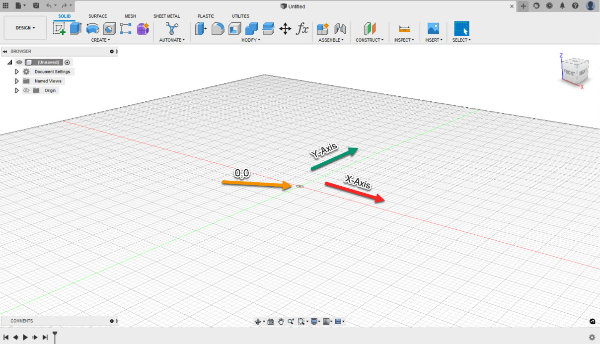
Figure 2.1 – Origin location on a grid

Figure 2.1 – Origin location on a grid

Choosing any tool in the toolbar, such as the Box tool under the SOLID tab within the CREATE panel, you will see three planes appear on your screen with a Select a plane or planar face option:
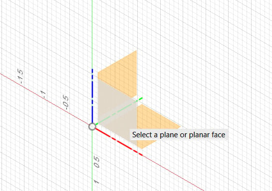
Figure 2.2 – Planes once a command has been chosen

Figure 2.2 – Planes once a command has been chosen

Think of these planes as your drawing paper, and you can choose which side of an object you want to draw on. These planes represent the top, side, and front views of your object.

Once you choose a plane by left-clicking on it, you can then draw the size of...

lock icon The rest of the chapter is locked
Register for a free Packt account to unlock a world of extra content!
A free Packt account unlocks extra newsletters, articles, discounted offers, and much more. Start advancing your knowledge today.
Unlock this book and the full library FREE for 7 days
Get unlimited access to 7000+ expert-authored eBooks and videos courses covering every tech area you can think of
Renews at $19.99/month. Cancel anytime
Banner background image