Exploring Arduino Uno
An Arduino Uno consists of a number of parts. The important ones are as follows:
USB port
External power supply port
Analog pins
Digital pins
ICSP
Microcontroller
Reset button
Let's know about them in detail.
USB port
This port is used to power up the Arduino board and upload programs into the microcontroller:
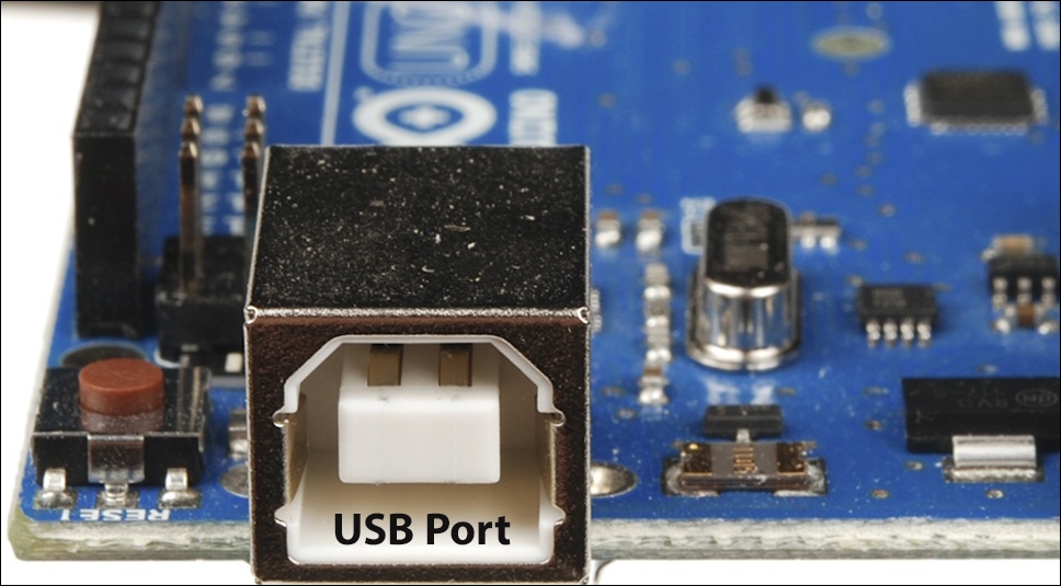
On the Arduino Uno, the USB port is situated in between the reset button and the voltage regulator.
A-B cable is needed for powering up the board and uploading code to the microcontroller. The following picture is an A-B cable:
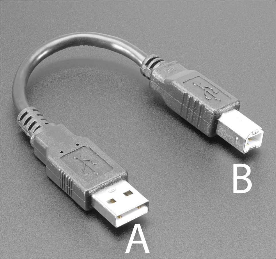
The 'A' side is connected to the Arduino board and the 'B' side is connected to the USB port of the computer.
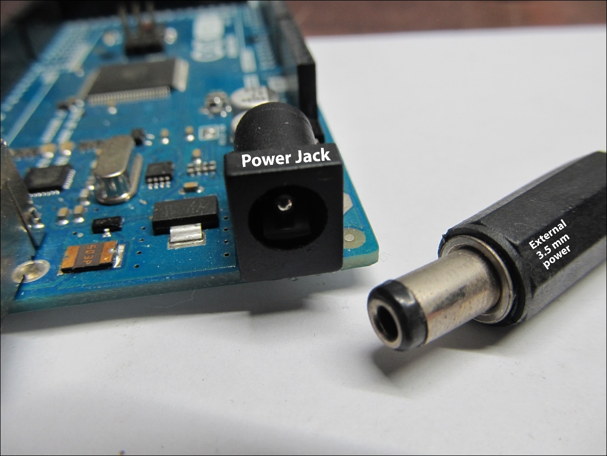
External power jack
Via this port, we can power the Arduino, but we cannot upload a program using it. This port is usually a 7-12 volt DC input. The following picture is a spare port and an adapter of 7-12 volts. The following picture is an external power jack and a port of 3.5mm power:
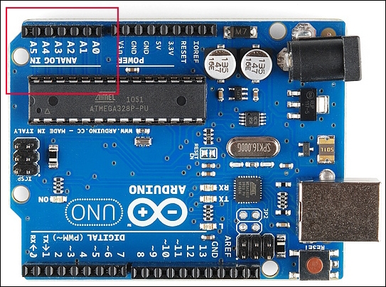
Analog pins
On an Arduino Uno, there are six analog pins (A0, A1, A2, A3, A4 and A5). The analog pins are used for reading analog values. We will discuss the uses of the analog pins in the next chapter.
The following image shows the analog inputs of the Arduino Uno:
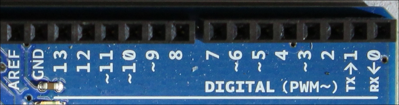
Digital pins
On an Arduino Uno there are 14 digital pins (0-13). The digital pins are used for reading digital values from sensors, generating digital signals and communicating with other devices through digital interfaces. The following image shows the position of the digital pins of the Arduino Uno:
ICSP
There are two sets of ICSP (In Circuit Serial Programming) pins on an Arduino Uno board. On the image below, you can see both of them (A and B). These ICSP pins are used for updating the firmware or reinstalling the bootloader, which is something you should not worry about in this book:
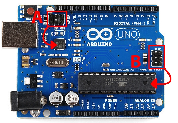
Note
Firmware is permanent software that is programmed on the read-only memory, and bootloader is a computer program that helps to load the operating system.
Microcontroller
There is a main microcontroller on our Arduino. By microcontroller we mean a single computer or a collection of processor core, memory and input/output peripherals. On our Arduino Uno we have ATmega328. Let's see the pin out of the microcontroller:
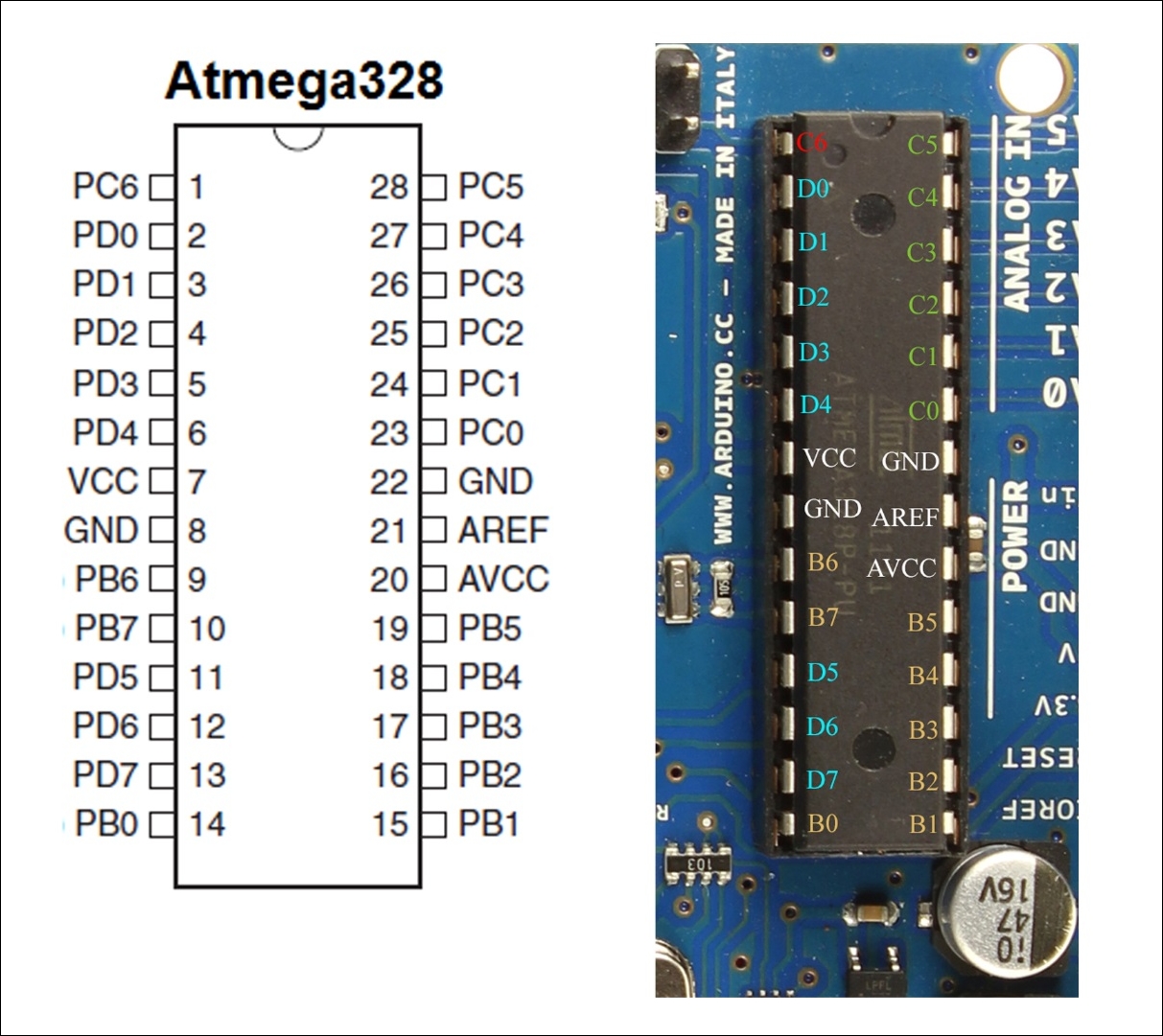
The pins are defined as follows:
|
Pin number |
Pin name on the microcontroller |
Pin name on Arduino |
|
1 |
PC6 |
Reset |
|
2 |
PD0 |
0 (RX) |
|
3 |
PD1 |
1 (TX) |
|
4 |
PD2 |
2 |
|
5 |
PD3 |
3 (PWM) |
|
6 |
PD4 |
4 |
|
7 |
VCC |
VCC |
|
8 |
GND |
GND |
|
9 |
PB6 |
Crystal |
|
10 |
PB7 |
Crystal |
|
11 |
PD5 |
5 (PWM) |
|
12 |
PD6 |
6 (PWM) |
|
13 |
PD7 |
7 |
|
14 |
PB0 |
8 |
|
15 |
PB1 |
9 (PWM) |
|
16 |
PB2 |
10 (PWM) |
|
17 |
PB3 |
11 (PWM) |
|
18 |
PB4 |
12 |
|
19 |
PB5 |
13 |
|
20 |
AVCC |
VCC |
|
21 |
AREF |
AREF |
|
22 |
GND |
GND |
|
23 |
PC0 |
A0 |
|
24 |
PC1 |
A1 |
|
25 |
PC2 |
A2 |
|
26 |
PC3 |
A3 |
|
27 |
PC4 |
A4 |
|
28 |
PC5 |
A5 |
Note
PWM means Pulse Width Modulation. This is a process by which we get analog results by digital means. GND is Ground, and VCC is the power (3.5V or 5V).
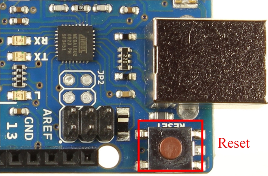
Reset button
On Arduino Uno there is a reset button between the USB port and the digital pins. The following pins show a reset button of Arduino Uno. This button is used to refresh the board or restart the system:
Now we know all we need about Arduino Uno, let's connect it to the computer and program for our Arduino Uno.
Connecting Arduino to PC
To connect Arduino Uno to our system we will need an A-B cable, about which we have already learned. Let's connect the Arduino as shown in the following image:
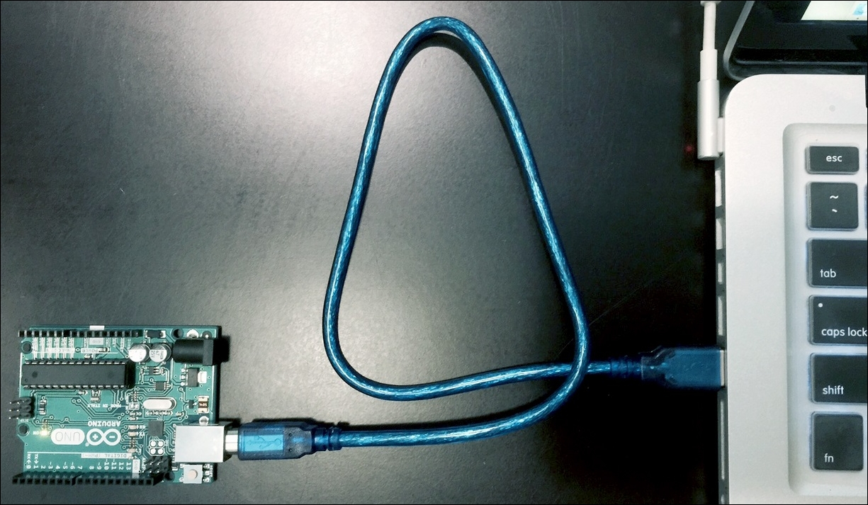
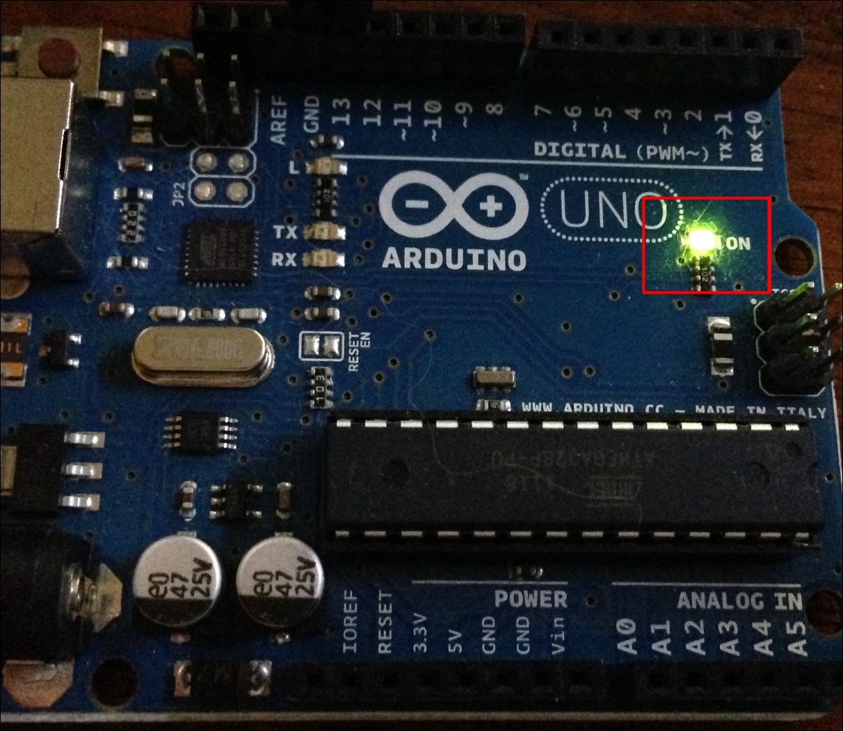
You will hear a sound on your system after connecting the Arduino Uno to the PC. A green light on the Arduino Uno will glow. If the green light does not glow, something went wrong. You need to check the connection or see Chapter 10, Few Error Handlings:
Now, we will download the IDE for coding for the Arduino and uploading to the board.