
How should grids intersect?
Our first example of intersecting grids will start with a simple grid, which you can see in Figure 2.20.
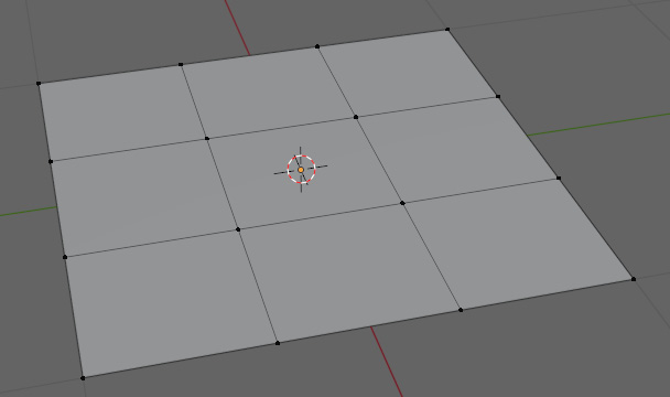
Figure 2.20 – Normal grid
To create a grid, as in the preceding figure, see the following:
- Go into Edit Mode.
- Perform a loop cut on the plane by pressing Ctrl + R.
- Scroll up once on the mouse wheel so that you have two loop cuts, resulting in Figure 2.21.
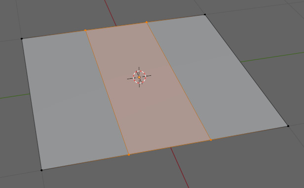
Figure 2.21 – Plane with two loop cuts
- Repeat this double loop cut perpendicular to the first cuts.
Now that we have a matching grid, we can tweak it to help illustrate an intersecting grid. We are going to extrude a face from the center of the plane to see how it affects the topology:
- First, select the center face.
- Press E to extrude the face.
- Move the mouse so that the selected face is pulled away from the rest of the faces to make an extrusion.
- Finalize the transform by pressing...