Exploring edges and faces
When it comes to what a model is made of in SketchUp, there are really only two pieces: faces and edges. I know that, eventually, you will end up with a model with groups, curves, polygons, and components, but those are just containers for edges and faces, which are building blocks that make up anything and everything that can be created in SketchUp:

Figure 1.3 – Edges and faces (left) make up everything on the right
For this reason, it is very important to understand how these items are created and work together in order to gain mastery of the 3D modeling process.
Edges are lines, right?
Technically, this is a true statement. Edges are a connection between two points in 3D space. In SketchUp, we call them edges because they generally define one or more faces, and the term line is reserved for a specific command.
Edges are created when you use any of the input commands but are most simply created using the Line command. The Line command, of course, connects two points in 3D space with a single edge. This can be useful for creating boundaries of faces or breaking them into smaller pieces.
Edges also make up curves, arcs, and circles. While you do not have to draw each individual edge when you create one of these entities, it is very important to note that they are all made up of a series of edges.
Edges in arcs and circles
When you use the Circle command or any of the Arc commands to draw a curved line in a model, you are actually creating a string of connected edges. In fact, any of these commands will allow you to define the number of edges before or after a circle or arc is created. The measurement box in the lower right of your screen will allow you to enter the number of sides before you start drawing. Once an arc or circle has been created, you can edit the number of segments in the Entity Info window. Changing this number will increase or decrease the number of edges drawn while keeping the geometry in the same place with the same curve.
Welding edges
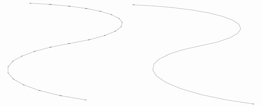
In SketchUp, you can select any number of edges and weld them using the right-click menu. Once one or more edges are welded, SketchUp will recognize them as a curve. A curve is a series of connected edges that are selected together and recognized as a single entity. This is different from an arc or circle though, as you cannot edit the number of segments in a curve, nor can you modify how many edges make up the curve, as shown here:

Figure 1.4 – With endpoints visible, you can see the difference between the segments on the left and the single-piece curve on the right
Let’s do an experiment:
- Use 2-Point Arc to draw an arc with the default 12 edges of any size.
- Select the arc and look at Entity Info. See how it calls it an arc and you have an editable Segments field?
- Now, right-click on the arc and select Explode Curve from the context menu.
Look at the Entity Info window now. You now have 12 edges selected. The option to modify the number of segments is gone.
- Finally, right-click on the highlighted edges again and choose Weld Edges from the context menu.
The Entity Info window now shows that you have a curve selected. It also tells you that the curve has 12 segments, but the field is disabled. This means that while you get to know how many edges are in the curve, you cannot modify that number.
So, why would you ever want to explode curves or weld them back together? The truth is, that sometimes, the modeling process will cause curves to explode. Intersecting geometry can break curves and circles and leave you will a bunch of disconnected edges. Using Weld Edges will get them to stay connected, making them easier to work with. This will also affect how these edges work with a command such as Push/Pull or Follow Me. There may also be times that it serves your model to have those edges broken apart rather than stay connected. The important thing to remember is that all this geometry, arcs, circles, and curves, is simply made of a series of edges that can be broken apart or put back together as needed.
Face or a surface?
A face is created any time three or more edges connect in a single plane. Unlike some other file formats, SketchUp faces can be made of any number of sides and may contain holes. As soon as an edge breaks a face into more than one piece, it becomes multiple faces.
If one or more faces are connected at the edge and that edge is smoothed (either using the Eraser with the Smooth modifier key or using the Soften/Smooth window) they will merge together, forming a surface. A surface is any number of faces that have been connected by smoothed edges. If you select a surface, the entire surface will be highlighted. If you choose to show hidden edges (from the View menu), you will see the hidden edges as dashed lines. In this view, you will be able to select individual faces, despite them being part of a surface.
It is important to know the difference between the two as certain commands, such as Push/Pull, cannot be used on surfaces. However, you can use Push/Pull on individual faces when hidden edges are visible!
Crossing faces
When you draw an edge across another edge, they break at the intersection. One edge crossing a second edge will result in four total edges, meeting at one central point. The same is not true for faces. Try this example:
- Draw a rectangle on the ground.
- Pan over and draw a vertical rectangle. Use the Right Arrow key to constrain the rectangle to the red plane.
- Select the vertical rectangle by the midpoint of a vertical side.
- Move it so that it crosses the face of the first rectangle.
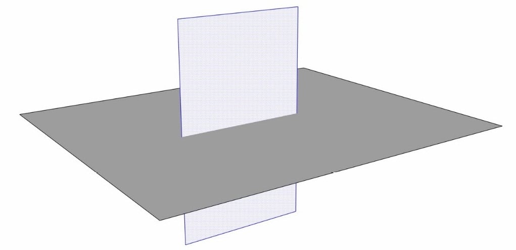
- Place the vertical rectangle so that the edges do not touch:

Figure 1.5 – Faces can cross without merging geometry
See how the rectangles cross over each other without merging together. At this point, you can select the vertical rectangle again by any point and move it out of the original rectangle. If you place the vertical rectangle so that the edge intersects any edge of the first rectangle, then the edges will become connected, and the faces themselves will still simply pass through each other.
To cause a face to intersect another face, you must tell it to intersect.
- With both rectangles crossing through one another, select both faces (use Shift + Select to highlight both).
- Right-click on either plane.
- Select Intersect Faces from the context menu.
- Select With Selection.
Notice how both faces are now broken where they cross each other. Edges will automatically connect to other edges, but faces will not.
As you advance with your 3D modeling skills, you will become more and more efficient using different native commands and extensions and will develop your own workflows for different types of models. The thing to remember though is that every single model is made of edges and faces. Knowing how these basic pieces work and interact is key to understanding how SketchUp works. Another key is in knowing how to use commands beyond their initial function. In the next section, we will see how to use a tool such as Move to perform multiple actions.


