Using interrupts to read the push-button state
The previous recipe explained how to read digital signals with the GPIO peripheral. However, the proposed solution is inefficient because the CPU wastes cycles waiting for the button to be pressed while it could do something else in the meantime. Furthermore, this could be a scenario where we would keep the CPU in low-power mode when there is nothing else to do.
This recipe will teach us how to read the push-button state efficiently by using the interrupts on the Arduino Nano.
The following Arduino sketch contains the code referred to in this recipe:
05_gpio_interrupt.ino:
Getting ready
Let's prepare this recipe by learning what an interrupt is and what Mbed OS API we can use to read the push-button efficiently.
An interrupt is a signal that temporarily pauses the main program to respond to an event with a dedicated function, called an interrupt handler or interrupt service routine (ISR). Once the ISR ends the execution, the processor resumes the main program from the point it was left at, as shown in the following diagram:

Figure 2.32 – Interrupt pauses the main program temporarily
The interrupt is a powerful mechanism to save energy because the CPU could enter the sleep state and wait for an event before starting the computation.
A microcontroller has several interrupt sources, and for each one, we can program a dedicated ISR.
Although the ISR is a function, there are limitations to its implementation:
- It does not have input arguments.
- It does not return a value. Therefore, we need to use global values to report status changes.
- It must be short to not steal too much time from the main program. We want to remind you that the ISR is not a thread since the processor can only resume the computation when the ISR finishes.
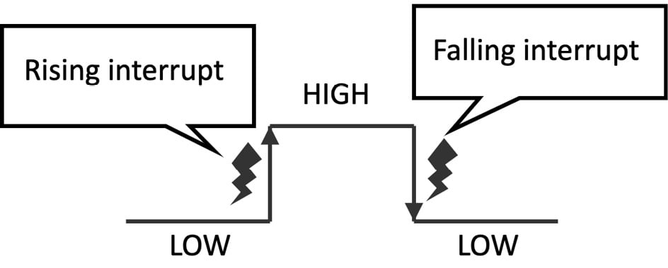
For GPIO peripherals in input mode, we can use the mbed::InterruptIn (https://os.mbed.com/docs/mbed-os/v6.15/apis/interruptin.html) object to trigger an event whenever the logical level on the pin changes:

Figure 2.33 – Rising interrupt versus falling interrupt
As we can observe from the preceding diagram, mbed::InterruptIn can trigger interrupts when the logical level on the pin goes from LOW to HIGH (rising interrupts) or HIGH to LOW (falling interrupt).
How to do it...
Open the sketch built in the previous recipe and follow these steps to turn on and off the LED with the GPIO interrupt:
- Define and initialize the
mbed::InterruptInobject with thePinNameof the GPIO pin connected to the push-button.
For the Arduino Nano:
mbed::InterruptIn button(p30);
For the Raspberry Pi Pico:
mbed::InterruptIn button(p10);
The mbed::DigitalIn object is not required anymore since mbed::InterruptIn also controls the interface with the GPIO peripheral in input mode.
- Write an ISR for handling the interrupt request on the rising edge (LOW to HIGH) of the input signal:
void rise_ISR() {
  led = 0;
}
The LED is turned off when the preceding ISR is called (led = 0).
Next, write an ISR for handling the interrupt request on the falling edge (HIGH to LOW) of the input signal:
void fall_ISR() {
  led = 1;
}
The LED switches on when the preceding ISR is called (led = 1).
- Initialize
buttonin thesetup()function:void setup() { button.mode(PullUp); button.rise(&rise_ISR); button.fall(&fall_ISR); }
We configure the mbed::InterruptIn object by doing the following:
- Enabling the internal pull-up resistor (
button.mode(PullUp)) - Attaching the ISR function to call when the rising interrupt occurs (
button.rise(&rise_ISR)) - Attaching the ISR function to call when the falling interrupt occurs (
button.fall(&fall_ISR))
- Replace the code in the
loop()function withdelay(4000):void loop() { delay(4000); }
In theory, we could leave the loop() function empty. However, we recommend calling delay() when nothing has to be done because it can put the system in low-power mode.
Compile the sketch and upload the program to the microcontroller.


