Search icon CANCEL
Subscription
0
Cart icon
Your Cart (0 item)
Close icon
You have no products in your basket yet
Arrow left icon
Explore Products
Best Sellers
New Releases
Books
Videos
Audiobooks
Learning Hub
Free Learning
Arrow right icon
Arrow up icon
GO TO TOP
Squeaky Clean Topology in Blender

You're reading from   Squeaky Clean Topology in Blender Create accurate deformations and optimized geometry for characters and hard surface models

Arrow left icon
Product type Paperback
Published in Dec 2022
Publisher Packt
ISBN-13 9781803244082
Length 248 pages
Edition 1st Edition
Tools
Concepts
Arrow right icon
Author (1):
Arrow left icon
Michael Steppig Michael Steppig
Author Profile Icon Michael Steppig
Michael Steppig
Arrow right icon
View More author details
Toc

Table of Contents (13) Chapters Close

Preface 1. Part 1 – Getting Started with Modeling and Topology
2. Chapter 1: Navigating and Modeling in Blender FREE CHAPTER 3. Chapter 2: The Fundamentals of Topology 4. Chapter 3: Deforming Topology 5. Chapter 4: Improving Topology Using UV Maps 6. Part 2 – Using Topology to Create Appropriate Models
7. Chapter 5: Topology on a Humanoid Head 8. Chapter 6: Topology on a Humanoid Body 9. Chapter 7: Topology on a Hard Surface 10. Chapter 8: Optimizing Geometry for a Reduced Triangle Count 11. Index 12. Other Books You May Enjoy

Understanding good topology using grids

Good topology is a mesh that deforms the way you want and makes the shape you want with the fewest number of triangles. The easiest way to get clean topology is by using a quad-based workflow. A quad is a face that contains four edges and four vertices. Although it is considered a single face, it is technically two triangles combined. This can be seen in Figure 2.1. Because you can manipulate the vertices individually, it must contain two triangles.
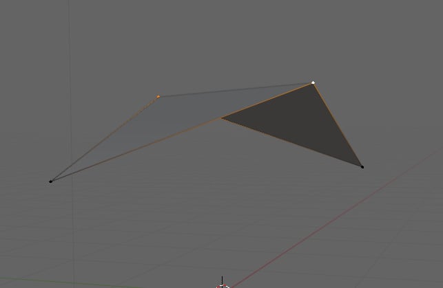
Figure 2.1 – Quad made up of two triangles

Figure 2.1 – Quad made up of two triangles

If you were to take multiple quads and string them together to form a plane, you would get a grid as shown in Figure 2.2.
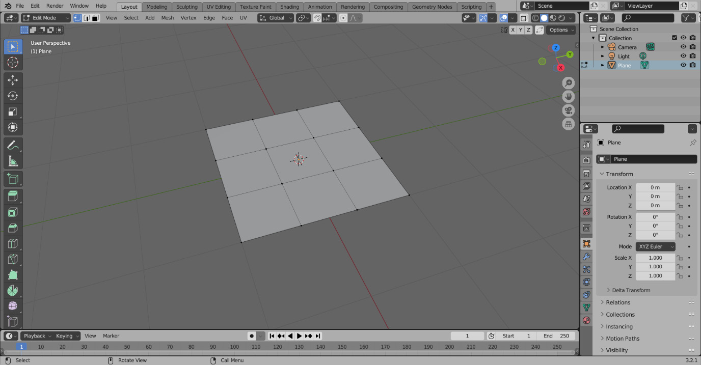
Figure 2.2 – A grid (the perfect topology for a plane)

If what you were planning to make was a plane, this would be an example of perfect topology. Unfortunately, objects and characters are often a bit more complex. Thankfully, there are a few useful tools we can use to help us check out topology using the grid as our example.

The most useful tool we have to check what our topology is doing is the Loop Cut tool. The Loop Cut tool adds a loop of edges through a row of connected faces. To use this tool, go through the following steps:

  1. To begin a loop-cutting operation, press Ctrl + R.
  2. After entering the operation, you can hover over a face and a line will appear along a loop of faces designating where the loop cut will take place – this is illustrated in Figure 2.3.
Figure 2.3 – Loop cut going through the plane

Figure 2.3 – Loop cut going through the plane

  1. To finalize the loop cut, press LMB, and to cancel it, press RMB. The finalized loop is shown in Figure 2.4.
Figure 2.4 – Finalized edge loop

Figure 2.4 – Finalized edge loop

  1. To add more loops to the cut, scroll up on the mouse wheel. To add fewer, scroll down, or you could press the number of loops you wanted on the number line and number pad.

For the purpose of checking the topology, we will mostly be using the guiding loop to see where our loops are going, so we will cancel the actual loop cuts. If we run a loop cut along one of the rows of faces shown in Figure 2.5, a few things are apparent.

Figure 2.5 – Loop cut for checking topology

Figure 2.5 – Loop cut for checking topology

  • First, the loop cut is actually going through the faces, showing us that our grid is properly made of quads
  • The second is that the line is going straight through the mesh, terminating on either end into the void
  • We can repeat this loop on every part of our grid, from every direction, and this is still true

However, one thing may cause issues here if you have started an extrusion on one of the points and then canceled it by pressing RMB. Because RMB does not remove the geometry created from the extrusion, you may be left with overlapping edges. In Figure 2.6, you can see what this might look like. Although it appears as though it is a clean grid, there is a duplicate edge blocking the loop cut.

Figure 2.6 – Broken loop cut caused by an extrusion

Figure 2.6 – Broken loop cut caused by an extrusion

This issue is usually solved by merging by distance. Merging by distance, also called Remove Doubles, merges the vertices of a selected mesh by the desired distance. To perform a Merge by Distance operation, see the following:

  1. Start by selecting the mesh with A.
  2. Press M to open the Merge tab.
  3. Then, select By Distance from the dropdown.

You can see the menu in Figure 2.7.

Figure 2.7 – Merge menu

Figure 2.7 – Merge menu

Another thing that can stop a loop from going through is a face flipped the wrong way. A face’s direction is determined by its normal. Normals are used to determine the direction in which the light will bounce off of a surface. A face has a front face and a back face determined by this normal. You can see a face normal direction by applying some settings in the Viewport Overlays tab shown in Figure 2.8. These settings are different in Object Mode and Edit Mode. For determining whether a face is flipped or not, check the Face Orientation checkbox in the Object Mode overlays tab. This will make all of the front faces blue, and all of the back faces red.

Figure 2.8 – Face Orientation checkbox

Figure 2.8 – Face Orientation checkbox

You can see the face that is flipped on this mesh in Figure 2.9 with Face Orientation enabled.

Figure 2.9 – Face Orientation revealing a flipped face

Figure 2.9 – Face Orientation revealing a flipped face

To change the orientation of a face, there are two options. You can press Alt + N to open up the Normals tab displayed in Figure 2.10.

Figure 2.10 – Normals menu

Figure 2.10 – Normals menu

In this tab, you can flip a selection of faces by selecting Flip at the top, recalculate faces on the outside of the mesh, or recalculate them on the inside. The most common option used here is Recalculate Outside. This option will fix flipped faces most of the time. The hotkey to recalculate the normals on the outside is Shift + N. In Figure 2.11, the face is fixed, and the loop goes through all of the faces as desired.

Figure 2.11 – Fixed normals

Figure 2.11 – Fixed normals

By now, you should have a basic understanding of how a grid works, and how we can check the topology of that grid to judge whether it constitutes good topology. However, to work on more complex objects and manipulate grids to improve the topology, we need a stronger understanding of the three rules of topology.

lock icon The rest of the chapter is locked
Register for a free Packt account to unlock a world of extra content!
A free Packt account unlocks extra newsletters, articles, discounted offers, and much more. Start advancing your knowledge today.
Unlock this book and the full library FREE for 7 days
Get unlimited access to 7000+ expert-authored eBooks and videos courses covering every tech area you can think of
Renews at $19.99/month. Cancel anytime
Banner background image