Planning to extend this robot
I rarely view robot projects as complete, especially those that are learning and development platforms. There are always new sensors to try, new programming algorithms to make, or simply bugs and quirks to iron out. On the other hand, there are ways to make robots more robust and cope with rougher environments, making the chassis lighter or the electronics simpler, so let’s start by considering some ideas for this robot and hopefully inspire some of your own.
Sensors you could add
The first exciting way to extend this robot is to add more sensors. Sensors are fun to program to get data from. This means you may have to figure out how to incorporate them into existing behaviors and mount them, though.
The following figure shows a selection of sensor extensions that could be interesting:
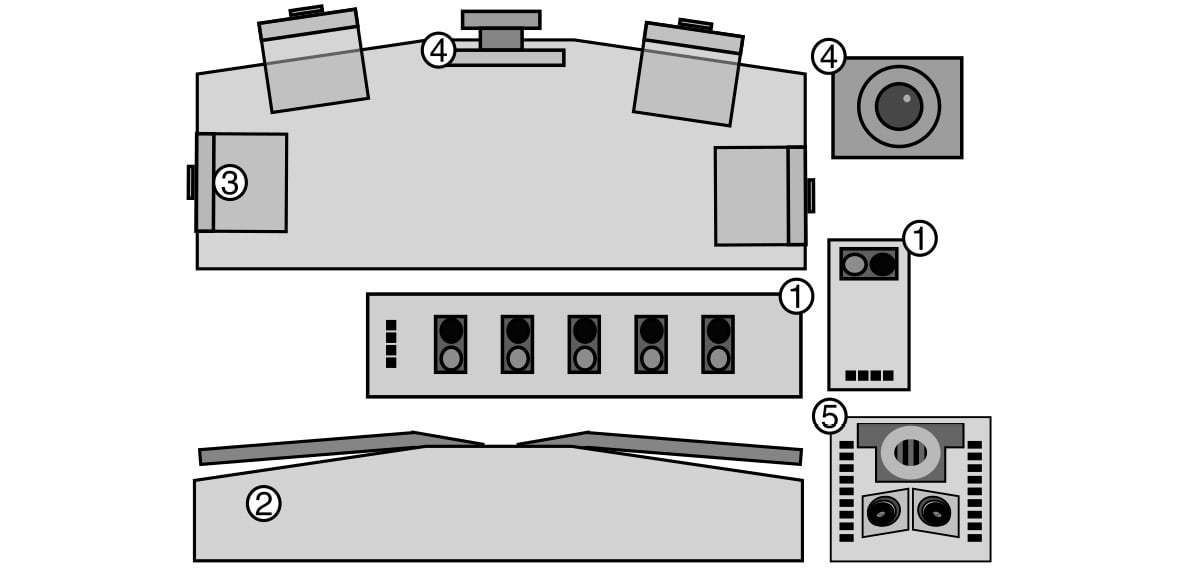
Figure 14.2 – Robot sensor extensions
The preceding figure shows a selection of sensors that would be great to extend this robot and the things you could get it to do. The sensor types are numbered:
- Line detectors or reflectance sensors: These light up with an Infrared (IR) LED and then detect how much light reflects from an object that they point toward, or how bright/dark it is. Makers mount these under the robot as a line-following sensor. Some sensors, such as the SunFounder 5-channel line sensor, come with arrays of light detectors, which can be used with code to follow a line drawn on a floor. An example of a single sensor type is a TCRT5000.
- Bump switches: Makers use these less in modern robots, and distance sensors should mean they aren’t needed. However, you could use them so that if a robot surpasses a safe distance and bumps into something, it will immediately disengage or move back. They tend to be simple on-off switches with long lever arms to extend the edge along which they sense.
- Additional distance sensors: We’ve used two sensors and moved them around. A set of four sensors would allow the different existing behaviors to be enhanced. It also offers more information for Monte Carlo simulation and could be used for a maze-following behavior.
- A camera: There are camera sensors that we could use with Pico, such as OV7670 camera modules. They are complicated to connect and may require an additional Raspberry Pi Pico. Using downscaling and running edge detection or ML algorithms on it, it is possible to match objects. A good alternative is cameras with onboard processing, such as the HuskyLens (https://bit.ly/3Dzurrb). Another type of camera is a FLIR IR heat camera.
- LIDAR sensors: These scan and return the depths of objects in their field of view. Having many distance sensors could extend the accuracy of Monte Carlo simulation. However, these produce a lot of data quickly and may need a more powerful CPU to control them. Solid-state sensors are low-power, small, and cheap. Pictured in Figure 14.2 is an LDRobot LD-07 solid-state LIDAR.
Light sensors can read how much light falls on them. You could use these to program behaviors that move toward or away from light or more complex interactions with light.
A robot can have internal sensors, such as thermal, current, and voltage monitors, to monitor its batteries and motors so that the code can respond to low-battery or high-current scenarios.
Optical flow sensors, such as the PAA5100JE, facilitate odometry based on the flow of the ground below a robot and can be used to detect the overall speed of the robot; this can compensate for issues such as wheels slipping, which encoders would miss.
We’ve covered some sensor ideas for our robot, but another way to get information to and from a robot is through user interactions.
Interacting with the robot
The robot in this book doesn’t have many options for user interaction:
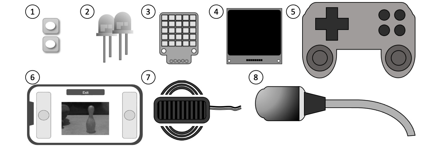
Figure 14.3 – Human interaction I/O
Figure 14.3 shows many ways to improve human interaction with the robot:
- Buttons: Add buttons for starting and stopping a behavior on a robot.
- LED lights: Some LED lights, perhaps with different colors, can be good to show a little feedback on what is running. Big LEDs can also be used as headlights.
- RGB LED displays: These come in strips or panels, and each LED can be set to a different color. They can provide more debugging and can make cute eyes or faces too. They use multiple interfaces, a custom one-pin system, and SPI or I2C. The Pimoroni PIM435 pictured uses I2C.
- OLED screens: These can show pictures, dials, menus, text, or graphics right on the robot. These come in mono or color varieties and are frequently I2C-controlled. One such mono I2C device is the Velleman WPI438 I2C screen.
- Game joypads: A game joypad controller would be a nice way to control a robot. However, it may require a more advanced Bluetooth setup to interface with Raspberry Pi Pico.
- A phone web app: We’ve been using the BlueFruit app, but by swapping Bluetooth for Wi-Fi (such as with Raspberry Pi Pico-W), you can write far more interactive phone control. This will require writing more code for a frontend. At the time of writing, a system for graphing on a smartphone requires a fair amount of code to produce over Wi-Fi, and a convenient app, such as BlueFruit LE Connect, doesn’t yet exist.
- A beeper: These can make beeping and buzzing sounds for the robot. You can drive some of these directly from GPIO pins, with musical tones indicating the program’s state or making interesting sounds.
- A microphone: There are UART-capable voice control modules suitable for Raspberry Pi Pico. They have a small set of commands to start behaviors, and, with LED or beeper feedback, could be a novel way to interact with the robot.
User interactions can manipulate behaviors, but we need somewhere good to mount these LEDs. What can we do to the robot’s chassis to improve and extend it?
Chassis and form enhancements
The robot’s chassis is simple and light, but we could take this much further, making it a more robust or aesthetically pleasing robot:
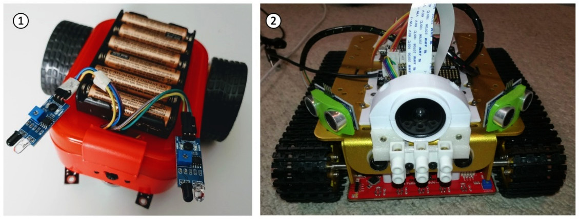
Figure 14.4 – Chassis enhancements
Figure 14.4 has examples of two ways to improve the robot or its sensors with an outer shell:
- Figure 14.4 (1) shows a lunchbox adapted into a robot. A lunchbox, ice cream tub, or roller paint tray with holes cut into it can be made into the fairing for the robot, enclosing the electronics and holding its wiring and electronics.
- Figure 14.4 (2) shows a robot with sensor mounts that have been 3D-printed. Custom fairings and brackets can be made this way or through vacuum forming or laser cutting. See the Design and manufacturing section later in this chapter.
Whichever method you choose, it needs to be lightweight and easy to remove so that the electronics are accessible and you can change the batteries. It could be held in place by bolts or Velcro.
You‘ll need to consider how to make controls accessible – such as putting switches and charging ports on the outside. Having a fairing invites more decoration, the use of color, and style paneling. Combining this with the RGB LEDs could make for an interesting-looking robot. You could take style cues from your favorite sci-fi robot and use a similar color scheme.
Electronics enhancements
The electronics we’ve used so far have been composed of modules tethered together with connector cables, using breadboards to assemble them. Breadboards are great for prototyping but take up a lot of space and weight and are susceptible to movement and vibration, with wires quickly coming loose or forming poor connections. They also look messy. What could we research to upgrade this?
Here are some sturdiness enhancements we can make to the robot electronics:
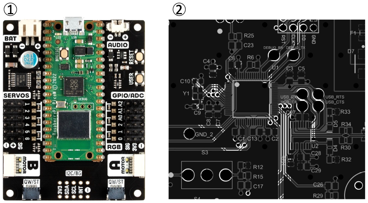
Figure 14.5 – Improving robot electronics
Electronics in the robot could be made smaller, lighter, and tidier. Try these ideas:
- Pictured in Figure 14.5 (1) is an Inventor 2040 W from Pimoroni (https://shop.pimoroni.com/products/inventor-2040-w). Motor and robot boards for Raspberry Pi Pico or incorporating an RP2040 will reduce the amount of wiring. The Inventor 2040 W includes motor control, lights, and servo connections.
- Soldered boards will be tidier. An intermediate option is using a stripboard or perfboard. These pre-made printed circuit boards can mimic the wiring arrangement of breadboard strips, allowing you to transfer breadboard designs onto them. You can then solder parts and wires into them. Wires going to external parts, such as motors and sensors, will have their connectors soldered into the board.
Figure 14.5 (2) shows a custom Printed Circuit Board (PCB) from https://github.com/uwrobotics/MarsRoverHardware. You can download or design your own using software such as KiCad. This is complicated but gives you lots of options for customization. You use a PCB view to lay out a circuit board and route connections between parts. Using PCBs allows you to make small, light, and tidy robot designs. In addition, it opens your designs to using surface mount electronics, which makes more components available. You can use design rules to ensure that the connections are all made and tracks are not touching. After this, you can then prepare the part for manufacture. You can take these designs to a board house, such as Seeed Studio (https://www.seeedstudio.com/), that prints the board for you.
Some board houses offer a Printed Circuit Board with Assembly (PCBA) service, where, at additional cost, they will solder on components, sockets, and connectors before sending the part to you. Using a PCBA service means you just need to plug in the external sensors and perhaps a Pico into a socket on receiving the board. That means that you do not need to solder surface mount parts yourself. Just be aware that this will take experience, and you may produce boards that aren’t right the first time.
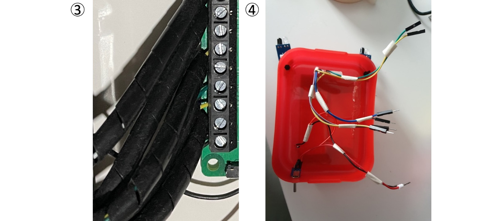
Figure 14.6 – Tidying wiring
- You can tidy robot cabling using 6 mm spiral wrap and cable clips, as shown in Figure 14.6 (3), or just masking tape, as shown in Figure 14.6 (4). Wiring can be aesthetically pleasing if you make an effort to route it nicely.
- For connectors, we have used Dupont connectors due to their convenience. However, once you are on a soldered circuit board, you can consider locking connectors, such as JST or Molex PicoBlade connectors. These lock cables in place so that they will not vibrate loose or easily be pulled out, and add further protection by being polarized. You will need to get practice with a crimping tool to use these effectively, but it will be worth it for better robot builds.
With a robust chassis and tidier electronics, perhaps you can get more ambitious with further outputs. Let’s see things you could make the robot’s outputs do.
Outputs you could add
Outputs mean a robot could do more to move or alter its surroundings. Additional motors, such as servo motors, can be used to make interesting mechanical devices, for example, those shown in the following figure:
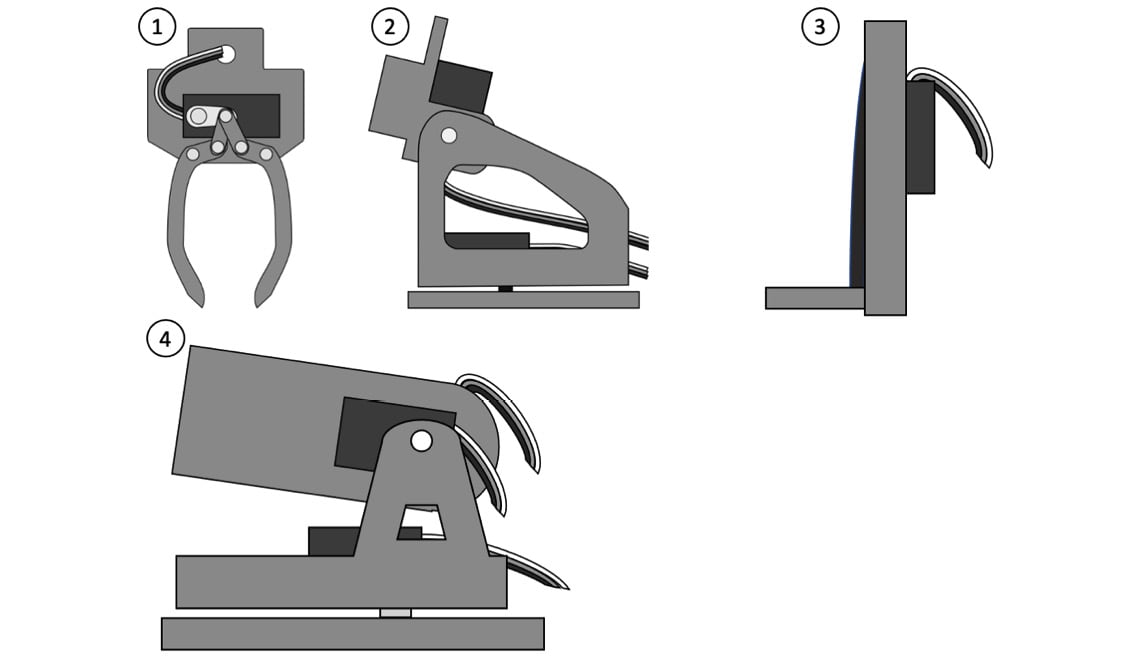
Figure 14.7 – Motors and outputs in use
Figure 14.7 shows a few interesting ways to use further motors to extend the robot:
- A gripper – This could grasp items and move them around. The Pololu Micro Gripper Kit uses a single servo to open or close the jaws. These are fun to attach to the front of a robot.
- A pan-and-tilt mechanism – Putting sensors on this means you can direct a sensor at a particular point of interest or use the head to sweep with a sensor. One servo motor rotates the head left and right (panning), and the other tilts the head up and down. The Adafruit Mini Pan-Tilt Kit is a good example of this.
- A lift-and-lower mechanism – These use a motor to lift and lower a platform, like a forklift. This could be combined with the gripper to make a robot that can stack objects.
- A ball launcher – A launcher would be fun so that a robot could aim at targets. Robotics competitions such as PiWars have events that involve using these. Motors are required to direct the aim, and a motor or actuator is required for launching the ball.
These are just a few examples; there are plenty more mechanisms you can either buy or build. You could even add a whole arm with a kit such as the MeArm Servo Robot Arm Kit.
Now that we’ve seen some outputs, perhaps we can better use these sensors and outputs with more behaviors.
Extending the code and behaviors
The robot’s code and behaviors are what bring the robot to life. However, there are many ways we could improve the code on this robot, as shown in the following figure:
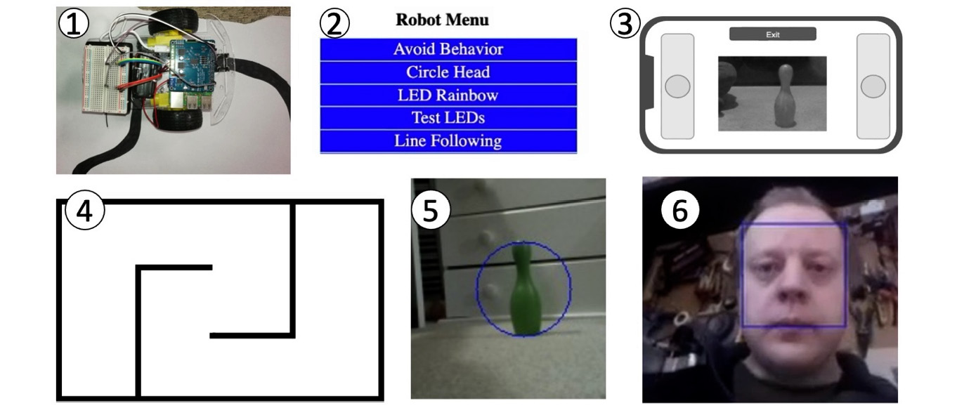
Figure 14.8 – Behavior suggestions
Figure 14.8 depicts some suggestions; the following list covers these and more:
- Line-following: Using the line detection sensors previously mentioned in the section on sensors, you could program a robot to follow lines drawn on the floor. Line-following can use if-then, bang-bang control, or a PID algorithm for smooth line-following.
- A menu system: You can combine all the behaviors in a menu for selection. Consider how each program would be tidied up so another can take over. A variation of this is using a voice control module, along with beeps, to indicate the current robot mode.
- Driving with a camera: Adding a camera and serving it to a phone web app means you could drive the robot with a camera view – a robot periscope.
- Maze solving: With more distance sensors, the robot would be able to look for openings and find its way around a maze. Depending on the complexity of the maze, simple rules such as always turning left might work, or the robot might have a map of the maze and use the Monte Carlo method with precision navigation. For example, a turning-left method using the encoders might be able to memorize what turns it took and where, backtrack, and try other routes.
- Camera navigation: Camera images can be scaled to low resolutions, and algorithms can be used to pick out features where image intensity or colors have changed over a threshold. The detected feature locations can then be combined with a PID algorithm to orient the robot relative to such features.
- Camera recognition: Recognition is considerably more complex and may require looking at a machine learning system such as TinyML. See https://bit.ly/3xy3twx for news on TinyML ports for CircuitPython. You can use similar techniques with microphones for speech recognition, but this may be intensive enough that multiple Raspberry Pi Pico boards would be required.
The following suggestions are not pictured but represent advanced behaviors:
- Simultaneous Location and Mapping (SLAM): A robot can use its sensors to build up a map of its location and then keep track of its pose relative to what it has already mapped. This technique would use several sensors together and benefit from the LIDAR sensors that we have already mentioned. However, this advanced technique can be a deep rabbit hole!
- Task planning and motion planning: Combining controlled turns, controlled movements, and location tracking with a hopper or gripper would mean you could make behaviors to seek out, collect items, and place them in a collection point.
These suggestions should hopefully inspire some creative behaviors. There are endless possibilities for combinations of code, sensors, and outputs, which you can use to improve your knowledge, solve problems with a robot, and extend your toolbox.
So far, though, these suggestions have been focused on extending the existing platform. So, what happens when we extend to thinking about your next robot platform?


