The different node connections and how to use them
Now that we’ve looked into the group input and group output nodes, let’s go over the various node connection inputs and outputs.
Let’s start by explaining the various input and output shapes in the Geometry Node editor.
Exploring different shapes
Let’s take a closer look at the input and output shapes in the Geometry Node editor.
The round node connection
This is what a round input/output node connection looks like:

Figure 1.4: The round input/output node connection
This is a round input/output node connection. This defines a single node value. For example, in geometry nodes, a single node connection can send through multiple values from other locations. With a round connection, this is not the case. This will likely result in the value being rounded to one value or returning an error value.
The squared input/output node connection
This is what a squared input/output node connection looks like:

Figure 1.5: The squared input/output node connection
It accepts multivalue fields. This means that every vertex on our mesh will be calculated separately according to the node tree. This feature in Geometry Nodes is very fun to play around with because each point gets its own flow of calculation, which opens up a world of interesting possibilities. An example of this feature is adding noise displacement to your mesh; each vertex will get its own displacement because each vertex is being calculated separately thanks to the square input/output node connection.
Exploring different node connection colors
Here’s an in-depth look at the different colors in the Geometry Node editor.
Boolean node connection
This node connection offers Boolean values.
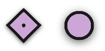
Figure 1.6: The Boolean input/output node connection
This node connection will define either an on or an off value; in other words, this is a value with either a 1 or a 0. As explained previously, this can either be a single value (circle shape) or multiple values (square shape).
Vector node connection
This is a vector node connection.

Figure 1.7: The vector input/output node connection
This carries three values combined into one. These values can be separated with a Separate XYZ node. It can also be combined with a Combine XYZ node. The vector node is used to define positions, rotations, scales, and offsets. It can also be used to define UV maps in the material node editor.
Geometry node connection
This is a geometry node connection.

Figure 1.8: The geometry input/output node connection
This defines geometry and instances. When you slide an object from the outliner into the Geometry Node editor, you will see this connection to add this instance to your Geometry Nodes project. This is also the connection you will see when you generate a point cloud with the Distribute Points on Faces node. This node will also show up on both sides when you use any geometry-modifying node, such as Transform Instance node, Scale Instance node, and any primitive mesh node. All of these nodes will be explained in Chapter 2, Understanding the Functionalities of Basic Nodes.
Integer node connection
This is the integer node connection.

Figure 1.9: The integer input/output node connection
This defines or accepts any value that is an integer; some examples of integer values are 0, 1, 2, 3, and 4. These values are basically values without a decimal point. These are usually used to define indexes of certain things, for example, duplicate objects. This node connection can be found on nodes such as the ID node, the Duplicate Elements node, and the Index node.
Value node connection
This is the value node connection, also known as the factor node connection.
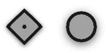
Figure 1.10: The value input/output node connection
This defines a plain value. The difference between this and an integer node connection is that the value node connection can contain decimal points. Some examples of nodes containing this node connection are the Noise Texture node and any math node. This value can also make use of multivalue fields, just like the square symbol we previously discussed.
Color node connection
This is a color value.
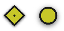
Figure 1.11: The color input/output node connection
This node connection contains three values, an R channel (red), a G channel (green), and a B channel (blue), also known as the RGB channels. These can be separated into their respective RGB values using a Separate RGB node. They can also be combined using a Combine RGB node. Just like the examples explained in the Exploring different shapes section, this node connection can also make use of multivalue fields.
String node connection
This node connection defines a string of text.
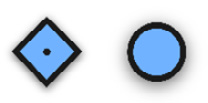
Figure 1.12: The string input/output node connection
This value will mainly be seen on nodes that are made to create or modify text, such as the String node, the String to Curves node, and the String Length node. This will be explained in depth later on in the book.
Material node connection
This node connection defines a material.
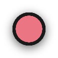
Figure 1.13: The material input/output node connection
It can be used to set the material of selected geometry in the node editor. This node basically refers to a material you’ve already made and one that is included in the project file. Some nodes that make use of this node connection are the Material node, the Set Material node, and the Replace Material node.
Multi-connection inputs
Let’s look into some special node connections.
Multi-Connection inputs allow you to connect multiple output connections into one input socket. This is generally used to join multiple datatypes of the same type into one output.
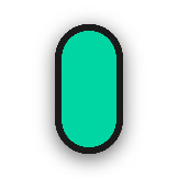
Figure 1.14: Geometry multi-connection input
The node connection seen here is usually used to combine elements; for example, the input shown in the preceding figure is used to join geometry together.
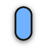
Figure 1.15: String multi-connection input
The preceding socket is used to join strings together. It works in the same way as the geometry multi-connection input.


