Search icon CANCEL
Subscription
0
Cart icon
Your Cart (0 item)
Close icon
You have no products in your basket yet
Arrow left icon
Explore Products
Best Sellers
New Releases
Books
Videos
Audiobooks
Learning Hub
Free Learning
Arrow right icon
Arrow up icon
GO TO TOP
Practical Autodesk AutoCAD 2021 and AutoCAD LT 2021

You're reading from   Practical Autodesk AutoCAD 2021 and AutoCAD LT 2021 A no-nonsense, beginner's guide to drafting and 3D modeling with Autodesk AutoCAD

Arrow left icon
Product type Paperback
Published in May 2020
Publisher Packt
ISBN-13 9781789809152
Length 826 pages
Edition 1st Edition
Tools
Arrow right icon
Authors (2):
Arrow left icon
Yasser Shoukry Yasser Shoukry
Author Profile Icon Yasser Shoukry
Yasser Shoukry
Jaiprakash Pandey Jaiprakash Pandey
Author Profile Icon Jaiprakash Pandey
Jaiprakash Pandey
Arrow right icon
View More author details
Toc

Table of Contents (17) Chapters Close

Preface 1. An Introduction to AutoCAD 2. Basic Drawing Tools FREE CHAPTER 3. Learning about Modify Commands 4. Working with Arrays and Reusable Objects 5. Managing Drawings with Layers and Properties 6. Working with Hatches, Text, and Dimensions 7. Tables, Isometric, and Parametric Drawings 8. Customization Tools 9. External References and Dynamic Blocks 10. Introduction to 3D Modeling 11. Creating Primitive 3D Shapes 12. Conversion between 2D and 3D 13. Modifying 3D Objects 14. Surfaces and Mesh Modeling 15. Paper Space Layouts and Printing 16. Rendering and Presentation

Using the Line command

You can select the Line command from the command bar, using its command alias, or you can also select the command from the ribbon panel. The Line command will make a straight-line segment of any specified length. This is the most basic of the draw tools and one of the most frequently used ones in the drawing workflow.

The Line command is in the Draw panel of the Home tab. To start the command, you need to left-click on its icon once or you can use its command alias, L. In this case, let's start the Line command from the ribbon panel:
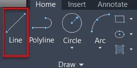
Figure 2.4: The Line command

Once your command is active, you will notice that the cursor will change into a point selection cursor that looks like two perpendicular intersecting lines and the command line will also show the name of the command, along with the prompt, as shown in the following screenshot:

Figure 2.5: The Line command with the command name and instruction
Where is the command line?

In case you are not able to see the command line/bar at the bottom of the drawing area, press the Ctrl + 9 keys to make it visible or to hide it.

Now, AutoCAD is ready for your input and you can start making the line. To do that, perform the following steps:

  1. Click on any point in the drawing area and the line will start from that point. Move your cursor and you will notice that the line will follow the movement of the cursor and it will stretch with the cursor, too. This line is also called a rubber bending line, which follows your cursor.
  2. Click on a second point in the drawing area and the fixed-length segment of the line will be made and the rubber bending line will again follow from the last point where you clicked. Repeat the process to make additional lines, and when you are done making the geometry, press the Enter or Esc key to exit the command.

This is the general workflow for making a random curve in AutoCAD but, as you have noticed, this method lacks precision as the distance was not specified for the line. To make drawings with precise distances, you need to use the direct distance entry method, which is explained in the next section.

Making lines with direct distance entry

In AutoCAD, direct distance entry is the most obvious way of making lines of precise length. This method is fairly easy, too. To explain this method, I will make a rectangle with a length of 7 units and a width of 5 units using the direct distance entry method and a line tool, as in the following example:

  1. Select the Line command from the Draw panel of the Home tab, as in figure 2.4, or type L and press Enter to start the command using its command alias.
  2. The command line will prompt you to specify the first point, as in figure 2.5. Click anywhere in the drawing area to add the first point of the line and let go of your mouse cursor and move your mouse elsewhere. The rubber bending line will be formed starting from the first point.
  3. Move your cursor in a horizontal direction and type a distance value. In this case, type 7 and press the Enter key again.
  4. The line will be formed in a horizontal direction with a length of 7 units.
  5. Now, move your cursor in an upward direction and again type another value. In this case, type 5 and press Enter. Another line in a vertical direction with a length of 5 units will be formed.
  1. Move your cursor again to the left, type 7, and press Enter again to make another horizontal line.
  2. Move your cursor down, type 5, and press Enter again. The line will return back to the starting point.
  3. The command will still continue and you will have a rubber bending effect of the line. Press the Enter or Esc key to exit from the Line command.

Once you are done with all the previous steps, you will have a rectangle that looks like the following screenshot. In this rectangle, the length is 7 units and the width, or height, is 5 units:

Figure 2.6: A rectangle using the Line command

This direct distance method is generally used to make drawings in AutoCAD and, as you have noticed, it allows you to make precise drawings as well. A similar workflow can also be used to make other geometries.

There are other methods of making drawings in AutoCAD and we will discuss these in the next section.

Making lines using absolute coordinates

Let’s take the example of this triangle shown here. In this case, all three coordinates of this triangle are labeled as point A, B, and C:

Figure 2.7: A triangle using the Line command

We will make this triangle in the following example using the Line command, but instead of direct distances, we will use coordinate values:

  1. Select the Line tool from the Draw panel or use its command alias, L, to start the command.
  2. The command line will prompt you to specify the first point for the line, as in figure 2.5. Type 0,0 for the first coordinate point, which is also the A point of the triangle, and press Enter.
  3. Now, we need to specify the coordinates of the second point, B. Type 10,0 and press Enter again. The cursor will move to the B point of the triangle.
  4. Once again, we need to specify the coordinates of the next point, C. So, type 14,7 and press Enter.
  5. Now, our cursor is at the C point and you can simply type 0,0 and press Enter to return to the first point, which is the origin. To exit the command, press the Enter or Esc key once.

As you have noticed, we only required the coordinates to make this triangle, but the coordinates are rarely used for making drawings and, in most cases, the length and angle values are predominantly used. In real-world drawings too, we will use direct distance entry primarily, but there will be a few instances where coordinates will also be used to make drawings.

In the next example, we will learn how to make a simple drawing using the polar coordinate system.

Using polar coordinates

Using polar coordinates, you can add distance and angle values directly to the command line and they need not be entered separately. To explain this, I will use the following diagram:

Figure 2.8: Adding a distance and angle

In this case, we need to draw a line that is inclined at an angle of 36 degrees with respect to the positive side of the X axis and has a length of 6 units. The following is the workflow for making this line:

  1. Type L and press Enter to start the line command.
  2. Type 0,0 and press Enter to start the line from the origin.
  3. Type 6<36 in the command line and press Enter.
  4. The line with a length of 6 units and a 36 degree angle with respect to the X axis will be made.

In this case, we started the line from the origin, and the distance from point A to point B is 6 units and the angle this line makes with respect to the positive side of the X axis is 36 degrees. So, you can add both of these values in the polar coordinate to form a DIS<ANG format, where DIS is the distance and ANG is the angle.

If, however, you start the line not from the origin, but from a random point in the drawing area and still want the same result, then you need to add an @ sign before the polar coordinates. This method is known as the relative coordinate system, which is explained next.

Using relative coordinates

To explain the relative coordinate system, I will once again use the same diagram that we used in the previous section, but in this case, the line will not start from the origin. Rather, we will start it randomly from any point in the drawing area, as in the following diagram:

Figure 2.9: Making a line using the relative coordinate system

So, the same line with a length of 6 units that is not starting from the origin and has an inclined angle of 36 degrees can be made using the following workflow:

  1. Type L and press Enter to start the line command.
  2. Click on any point in the drawing area to start the line.
  3. Type @6<36 in the command line and press Enter.
  4. The line with a length of 6 units and a 36 degree angle with respect to the X axis will be made.

This @ sign represents the relative coordinate system, which allowed us to make a line from a point that is not on the origin. Here is another example of relative coordinates.

As explained in the previous example, relative coordinates are helpful when you are making a drawing from a point that isn't the absolute origin and still want to use the selected point as a reference for adding the coordinates. In this example, I will create the following triangle using relative coordinates:

Figure 2.10: Triangle to be made using the relative coordinate system

Here, you can start the drawing at point A, which is not on the origin, and then progressively make your drawing by entering distances. Instead of direct distances, however, we will use relative coordinates to make this triangle in the following example:

  1. Start by selecting the Line command and then click on a point in the drawing area, making sure that the point is not at the origin. Let’s call it point A. As the A point is chosen randomly, we can’t specify an exact value of the (X,Y) coordinate for the B point with respect to the A point. So, in this case, we can use relative coordinates to specify a coordinate value of the B point with respect to the A point. Relative coordinates assume that the last point you clicked or selected is the origin and then make all measurements from that last point as if that point were the origin.
  2. So, if point A were the origin, then point B should be 8,0, with respect to point A. To make the AB horizontal line, type @8,0 and press Enter. The line will end up at point B, as in figure 2.10. Note the @ sign before the coordinate value. This @ sign is added to indicate that the next coordinates are "relative" with respect to the point that we previously clicked, which is the A point, in this case, and it will assume the A point as the origin instead of the absolute origin of the drawing.
  3. Once you have reached point B, don’t exit the line command, but type @0,6 and press Enter. You will notice that AutoCAD will reach point C, as in figure 2.10, and in this case, the B point will also be treated as the origin and the coordinate value of the C point with respect to the B point is 0,6, which is shown with the @ sign.
  4. You can complete the triangle by clicking again on the A point and then pressing Enter to exit the line command.

So, now that we have seen different methods of making the drawing in AutoCAD, let’s use a combination of these methods to make a simple drawing.

Making a drawing without coordinate values

So far, we have used different coordinate systems to make a drawing, but it is generally not the ideal way of making drawings in AutoCAD. Generally, we would use direct distances and angles instead. In this section, we will learn how to use this method to make drawings. To explain this example, I will use this triangle:

Figure 2.11: A triangle to be made using the direct distance entry method

In this drawing, there is no coordinate information provided and we will use only the dimension values, such as the length and angle, provided here to make it. We will make this triangle performing the following steps:

  1. Open a blank drawing and start the line command by clicking on the Line tool in the Draw panel, or by using the L command.
  2. Click at a point in the drawing area to start the rubber bending line and move your cursor toward the right side. Type 10 in the command line and press Enter.
  3. Press Enter again to exit the command.
  1. Click again at the starting point of the line (point A) and type <30, and then press Enter. Notice the < angle sign before 30. In this case, entering the angle sign before 30 will tell AutoCAD to take the numeric value as an angle and not a distance. Once you press Enter, you will notice that the line will be locked at an angle of 30 degrees with respect to the positive side of the X axis.
  2. Move your cursor in the direction of the 30 degrees line and type 14, and then press Enter again. This will make a line at an angle of 30 degrees with a length of 14 units.
  3. Click on the B point, as in the preceding diagram, and press Enter again to exit the command.

In this case, you saw that geometry can also be made by entering values of the distance and angle directly in the command line. This method is relatively easy when compared to the coordinate entry method. This is also the most common way of making drawings in AutoCAD. There are also some status bar modes that help you to generate references that can be used to make precise drawings. These modes are Dynamic Input, ortho, and polar tracking, and we will discuss them in the next section.

You have been reading a chapter from
Practical Autodesk AutoCAD 2021 and AutoCAD LT 2021
Published in: May 2020
Publisher: Packt
ISBN-13: 9781789809152
Register for a free Packt account to unlock a world of extra content!
A free Packt account unlocks extra newsletters, articles, discounted offers, and much more. Start advancing your knowledge today.
Unlock this book and the full library FREE for 7 days
Get unlimited access to 7000+ expert-authored eBooks and videos courses covering every tech area you can think of
Renews at $19.99/month. Cancel anytime
Banner background image