Understanding the SOLIDWORKS interfaces
The main focus of this section is to briefly introduce the SOLIDWORKS interfaces. Since we are going to be interacting with the interface in the rest of the book, only a few of the features are examined. Nonetheless, it is worth pointing out that the SOLIDWORKS Simulation interface is closely linked with the SOLIDWORKS modeling environment, and both require that you have the correct license. With SOLIDWORKS installed on your PC or laptop, the interfaces are accessed by following the steps laid out in the subsections that follow.
Getting started with the SOLIDWORKS modeling environment
This subsection illustrates a brief interaction with the SOLIDWORKS 2021-2022 modeling environment. The steps focus on the use of a single-part component to reveal the simulation environment. Let's start by launching the SOLIDWORKS application and then navigating to the modeling environment by following these steps:
- Choose File from the main menu.
- Click on New.
- Select Part and click on OK:
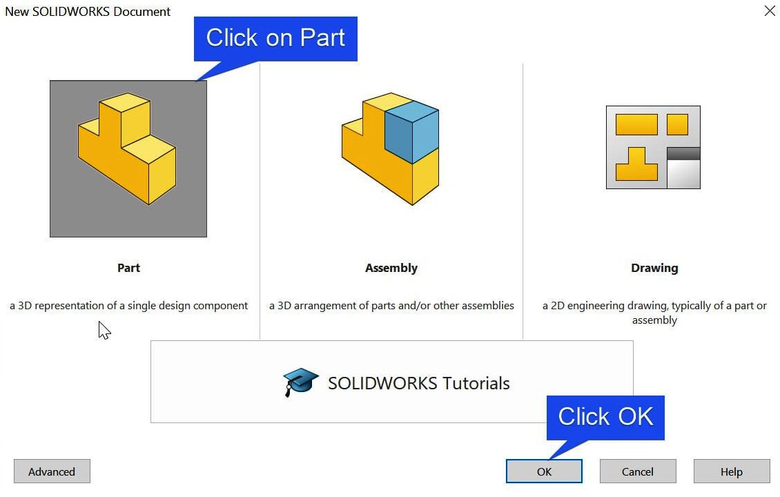
Figure 1.3 – The steps for launching the modeling environment
The modeling environment is launched after completing the preceding steps, as shown next. Generally, the modeling environment features many items, as shown in Figure 1.4. This includes the following:
- Menu Bar: This provides access to different kinds of commands that the software offers.
- Command Manager Tab: This encompasses a series of tabs segregating the commands for many specialized tasks.
- Feature Manager Tree: This acts as a record of features that are created in the graphics window, often representing these features in the order in which they are created.
- Document Window: This is used to navigate between different windows in the graphics area.
- Graphics area: The major area for modeling and simulation activities:
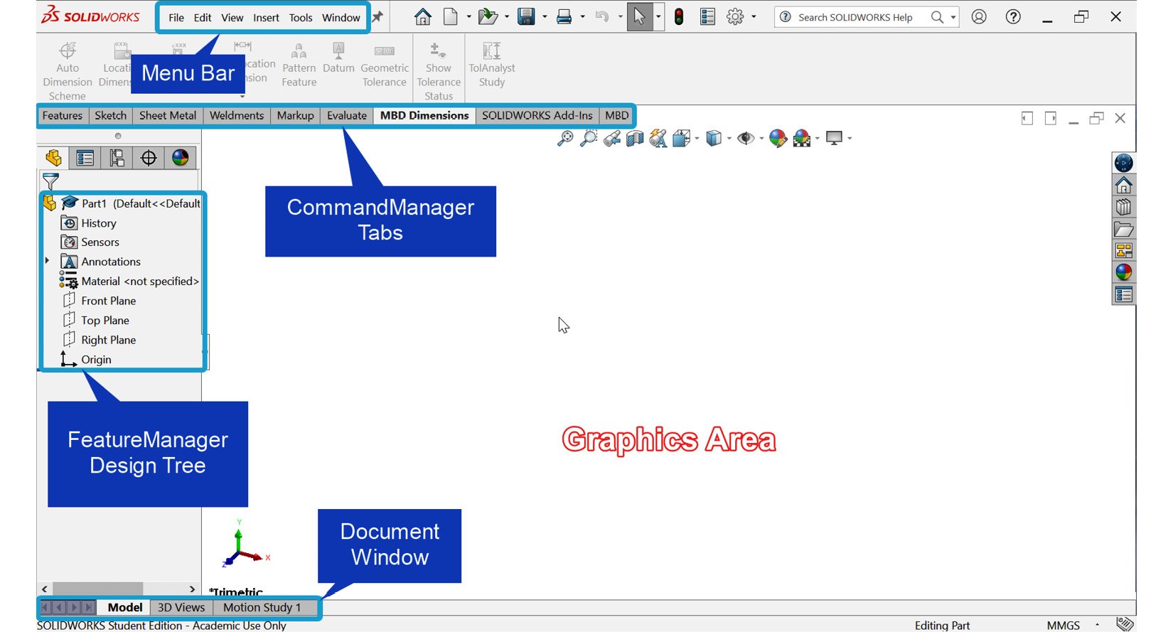
Figure 1.4 – The SOLIDWORKS 2021-2022 user interface
With the basic information about the interface detailed, let's now take a brief look at how to activate the simulation environment. We will come back to this activity in subsequent chapters in more detail.
Activating the SOLIDWORKS Simulation environment
Launch the SOLIDWORKS Simulation interface by following these steps:
- Activate the simulation add-in by performing the following:
- Clicking on the SOLIDWORKS Add-Ins tab (please refer to Figure 1.5).
- Selecting SOLIDWORKS Simulation:

Figure 1.5 – Activating the SOLIDWORKS simulation add-ins
The Simulation tab becomes active, as shown next. However, notice that when the SOLIDWORKS Simulation becomes activated, most of the icons are gray, as shown in Figure 1.6. This arises from the fact that no analysis has been defined yet.
- Start a new analysis by performing the following:
- Open a CAD model of a part or a component to be analyzed.
- Click on New Study, as shown in Figure 1.6:
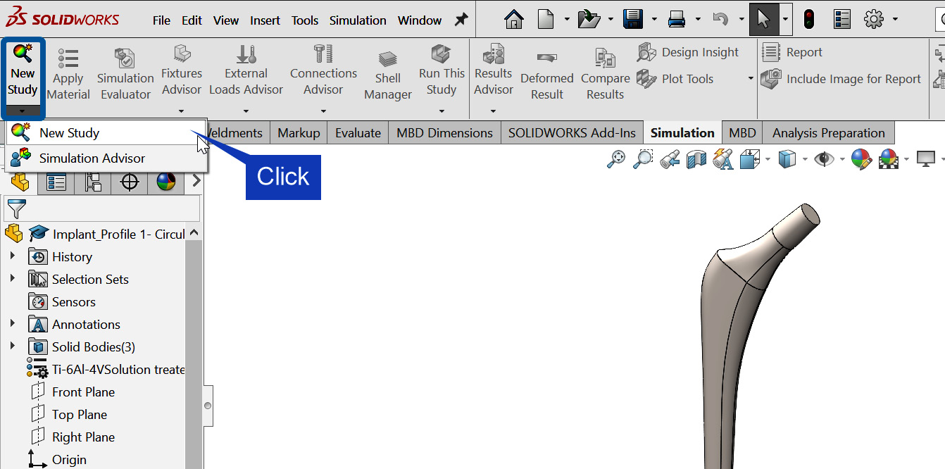
Figure 1.6 – Starting a new simulation study
- Select a Study type (in this book, we will be restricted to static analysis).
- Supply a descriptive name for the simulation study, as shown in Figure 1.7.
- Click on OK:
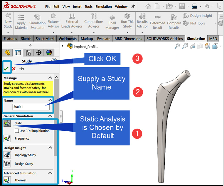
Figure 1.7 – Supplying the details of the simulation study
In response to the preceding steps, the simulation study environment is activated, as indicated in Figure 1.8. There are a few things to pay attention to in this screenshot. For one, the different icons that were previously gray underneath the Simulation tab in Figure 1.6 are now active in Figure 1.8. Further, the simulation tree manager and the study tab (at the base of the screen) have both appeared:
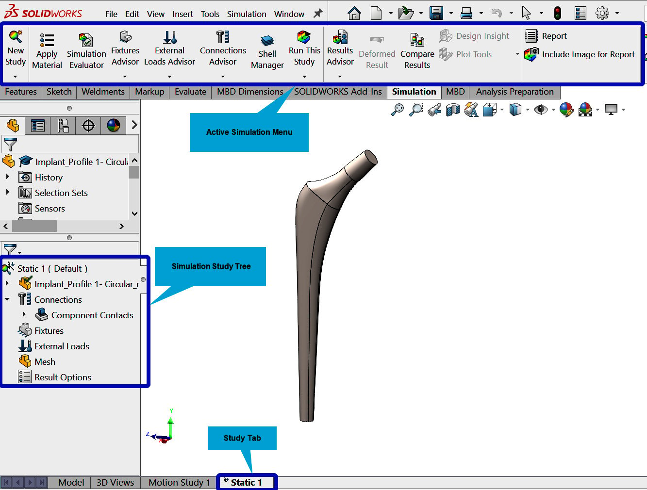
Figure 1.8 – Simulation study tree
The SOLIDWORKS Simulation environment is better explored within the context of simulation problems. Accordingly, rather than detailing all the features here, we will further examine them comprehensively in subsequent chapters and reveal the power of this simulation engine for the analysis of various types of problems.
In the next section, we will briefly highlight some of the important updates in SOLIDWORKS Simulation 2021-2022.


