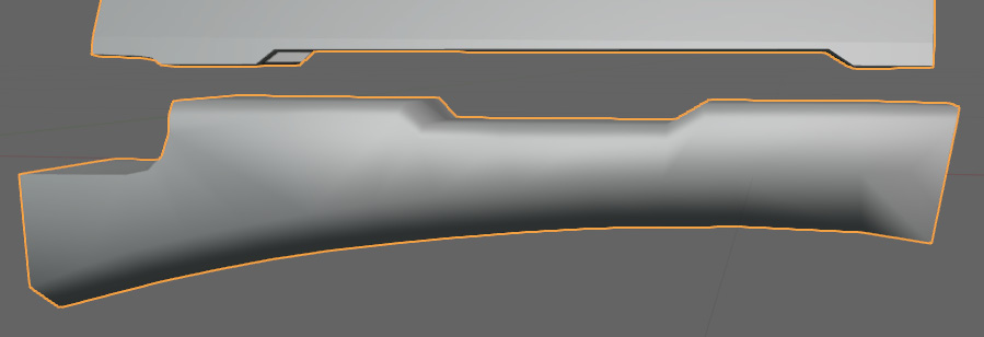
Retopology of the front grip
The next part of the blaster we are going to look at is the front grip. Figure 7.30 shows a close-up of the front grip.

Figure 7.30 – The front grip
Again, we are going to lay out the lines on our edges and corners first. You can see the guiding edges in Figure 7.31.

Figure 7.31 – Guiding edges
Next, we are going to start making the faces of the front grip. Most of the faces are going to be easy to place, but we should focus on the radius at the top left of the grip. You can see that there are far more vertices on the radius than the surrounding mesh. To address this, we just need to send the loops around the bottom of the grip. Figure 7.32 shows the finished faces.

Figure 7.32 – Guiding edges joined with faces
After adding new geometry, you may need to smooth the model again. The smoothed faces can be seen in Figure 7.33.


