Driving a robot from IMU data
In previous chapters, we saw how to use the PID algorithm, and in this chapter, how to detect a pitch, roll, and yaw from a magnetometer. Our robot can't move its pitch or roll, but it can change its heading.
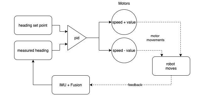
In this demonstration, we'll get the robot to stay on course—to try to track North regardless of where we turn it. Let's see how. Have a look at the following diagram:

Figure 16.19 – Drive to heading behavior
Figure 16.19 shows the flow of data. The left of the diagram starts with a measured heading, and a heading setpoint going into a PID—the error value will be the difference between the two. The measured heading has come from the IMU + Fusion algorithm. We use the PID output to drive the motors so that they move at a fixed speed plus or minus the value, so the robot will turn to reduce the error. The robot moving will feed back into the IMU + Fusion algorithm, looping through...


