Inspecting Mesh bodies and repairing them
STL is a simple file format and is widely used in 3D printing. Almost all 2D and 3D design software has been able to create STL files since its invention back in 1987. Because of its simplicity, long history, and wide availability, most STL files in existence contain errors and are generally in need of repair before they can be used for manufacturing.
In this section, we will learn how to inspect the mesh bodies we insert into Fusion and how to repair broken STL files using automatic and manual repair techniques, in order to prepare them for 3D printing.
To demonstrate the various methods we can use to inspect and repair mesh bodies, we will use an STL file called Clip_Broken.STL. Let’s start by creating a new Fusion design, as shown in Figure 1.14.
Now, we can use the Insert Mesh command and insert the Clip_broken.STL file into our active Fusion design document. Just like the last example, let’s utilize the Center and Move To Ground functionalities in the Insert Mesh dialog consecutively to translate the part closer to the origin and above the XY plane. Now, we can look at the details of the mesh body we just inserted.
Fusion automatically inspects all mesh bodies inserted and displays a warning icon next to any problematic mesh body. As shown in Figure 1.16, if you expand the bodies list in the browser, you will see a mesh body named Clip_Broken, and next to it, you will see a warning icon. If you hover over the warning icon, you will see the following information about the mesh body:
- Mesh is not closed.
- Mesh is not oriented.
- Mesh does not have positive volume.
When we see such information, we often need to take repair actions before we can proceed to 3D-print the files:
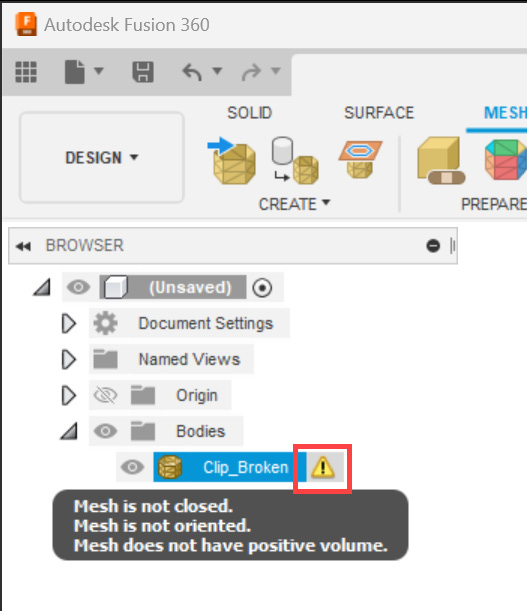
Figure 1.16 – A warning icon next to a problematic mesh body
Another useful tool for inspecting problematic mesh bodies is the PROPERTIES dialog. If you select a given mesh body, right-click, and select Properties, you can see a detailed list of information about the mesh body, as shown in Figure 1.17.
In this example, you can see that this mesh body does not have a mass or volume, even though it has been automatically assigned a physical material (Steel) with a density. This is another indication that this mesh body does not enclose a volume. Refer back to Figure 1.15, which shows the logic behind the automatic material assignment within the Material subsection of the Fusion Preferences dialog.
Important note
A common term used in 3D printing to describe bodies that properly enclose a volume is watertight. Having a watertight body is a desirable feature when attempting to 3D-print objects. However, just because an object is not watertight does not mean it is not 3D-printable. In metal powder bed fusion 3D printing, support structures are often made up of surfaces (not watertight bodies). We will cover this topic in more detail in Chapter 12.
If you expand the Mesh subheading, you will see that this mesh body has two shells. A shell is a collection of triangles (and sometimes quadrilaterals) that are connected to one another. If a mesh body is made up of multiple shells, it often indicates a broken continuity of the triangles that make up a mesh body.
Sometimes, a mesh body can have multiple shells and still be valid. For example, imagine a hollow sphere. In such a case, you would have one shell that represents the outside of the sphere and another shell that represents the inner boundary.
If you expand the Mesh Analysis subsection, you will see that this mesh body is not closed, not oriented, and does not have a positive volume:
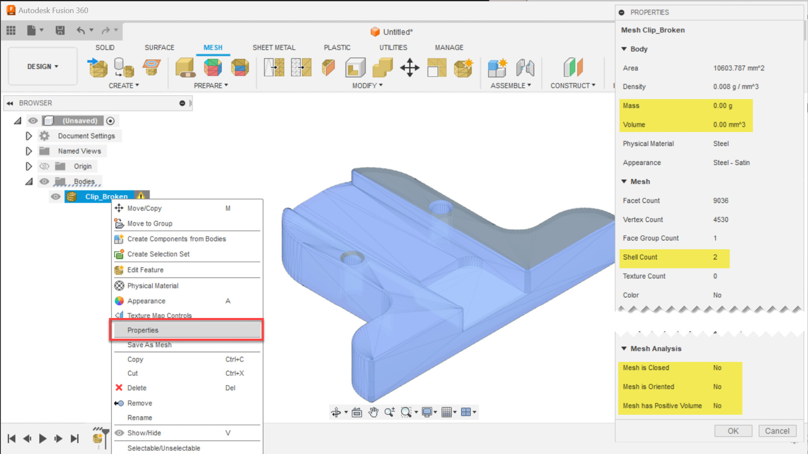
Figure 1.17 – The PROPERTIES dialog shows the relevant mesh analysis information
Now that we understand we have a problematic mesh body on our hands, we can close the PROPERTIES dialog, and select the Repair icon on the ribbon in the MESH tab | the PREPARE panel.
Fusion has four automatic repair types. Let’s start by selecting the Close Holes repair type, which fixes flipped triangles and closes holes. If we activate the preview checkbox within the REPAIR dialog and expand the detailed analysis, we can edit the sliders to see the impact of the selected repair type on the body we wish to repair. Figure 1.18 shows that this repair type will automatically fix the part so that it can be 3D-printed, but a visual inspection of the outcome looks cluttered, with many triangles overlapping each other.
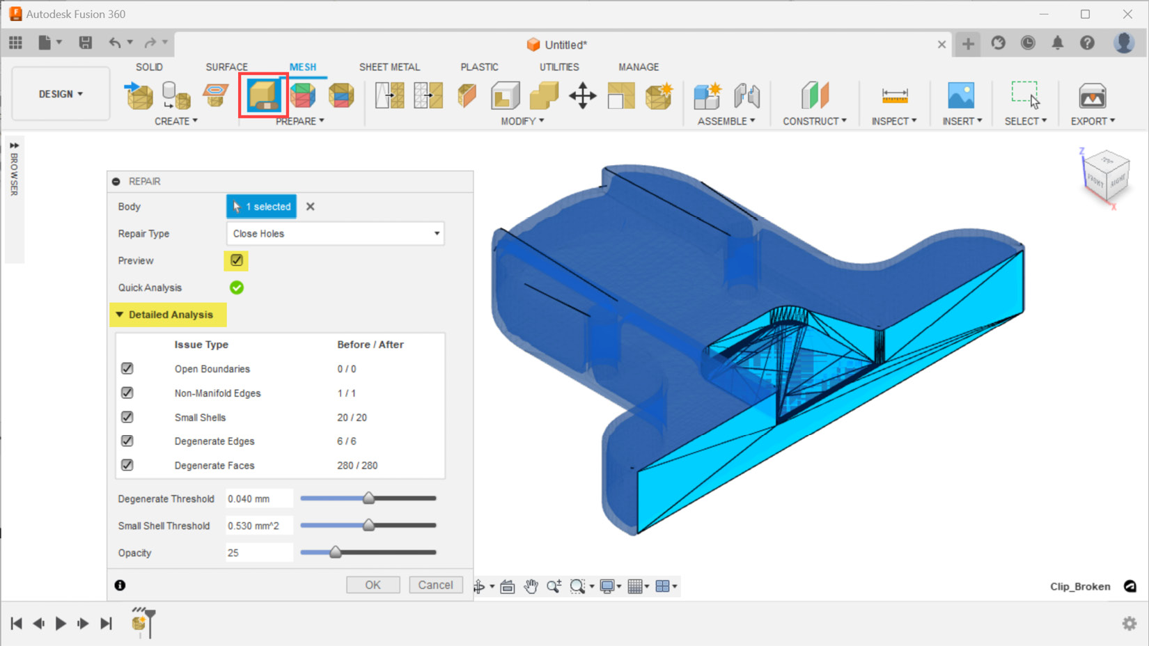
Figure 1.18 – The Close Holes repair type and its impact on this part
Even though the outcome of this automatic repair is reported as a success, it is always a good idea to perform a visual check and review the details of the mesh body properties. Figure 1.19 shows the PROPERTIES dialog for the Clip_Broken mesh body after we performed the Close Holes repair type. Here, we can see that this mesh is made up of 66 shells. This is an unexpected outcome, and a visual inspection of the part shows problematic zones, as highlighted in red ovals. This part is a symmetrical part along the XZ plane, yet the automatic repair closed one of the holes instead of creating the desired countersink hole type outcome:
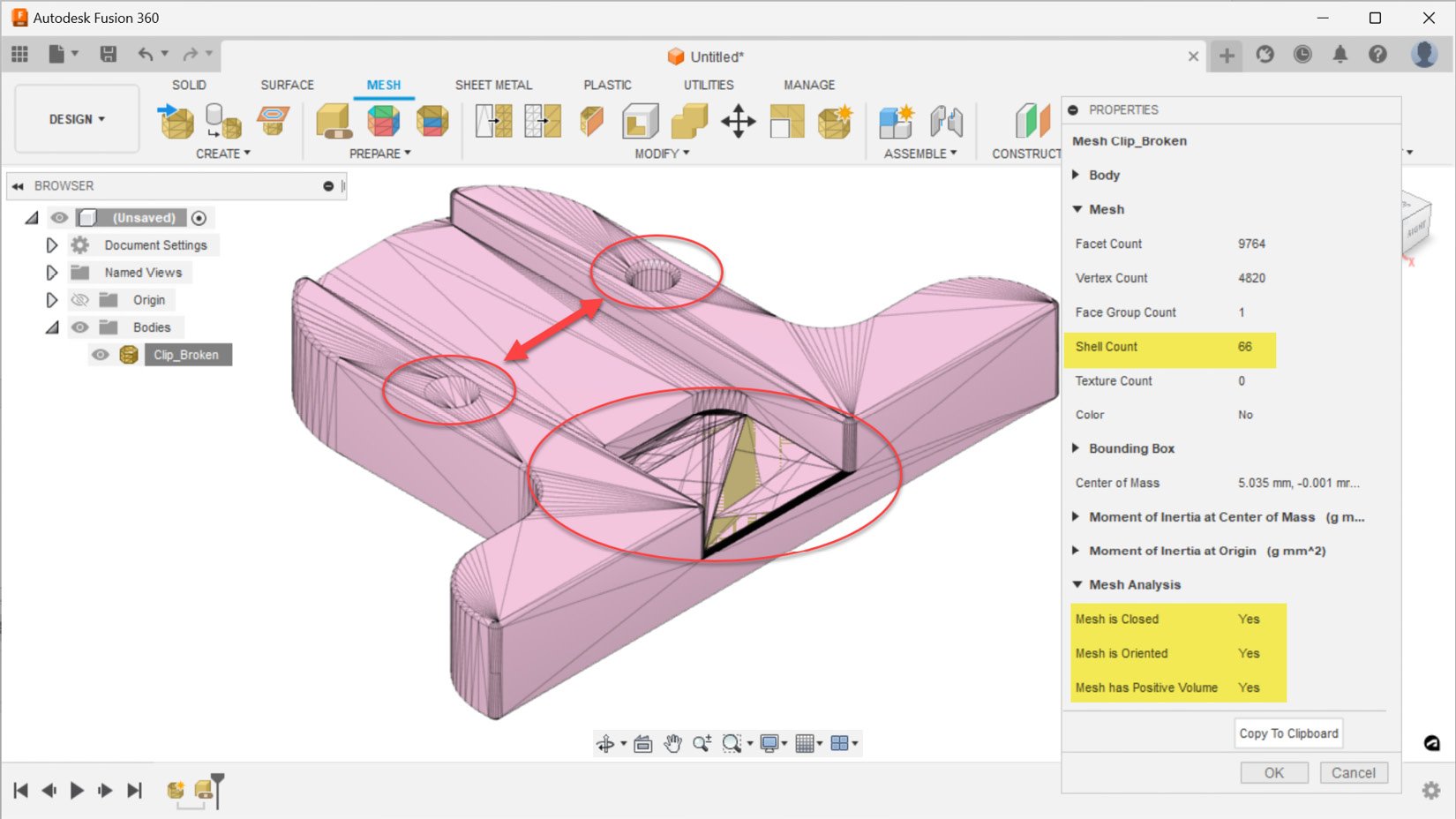
Figure 1.19 – The PROPERTIES dialog shows the outcome of repaired mesh body
Now, let’s use the Edit Feature command on the repair action we just performed, by selecting it from the timeline at the bottom of Fusion's user interface and right-clicking on it, as shown in Figure 1.20. This time, we can change our repair type to Stitch and Remove. This repair action includes all the repairs that the previous repair type executed, and stitch triangles remove double triangles and degenerate faces, as well as tiny shells. Using this repair type takes a little bit longer, but the outcomes look much better. As you can see in Figure 1.20, we no longer look at a cluttered mesh in the region highlighted with the large red oval. However, we still have the same issue of not having the desired outcome of the countersink hole:
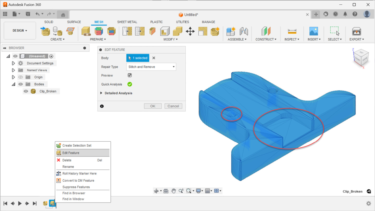
Figure 1.20 – The Stitch and Remove repair type and its impact on this part
Before we move on to the next repair type, let’s take a closer look at our part by adding a section analysis. To add a section analysis, we must use the Section Analysis command located in the INSPECT panel. After we select the cut plane as the XZ plane and flip the segment we want to section, we can easily see that this mesh represents a hollowed-out object, as shown in Figure 1.21. Looking at our part with a section analysis, it makes more sense why we saw a shell count of two within the PROPERTIES dialog:
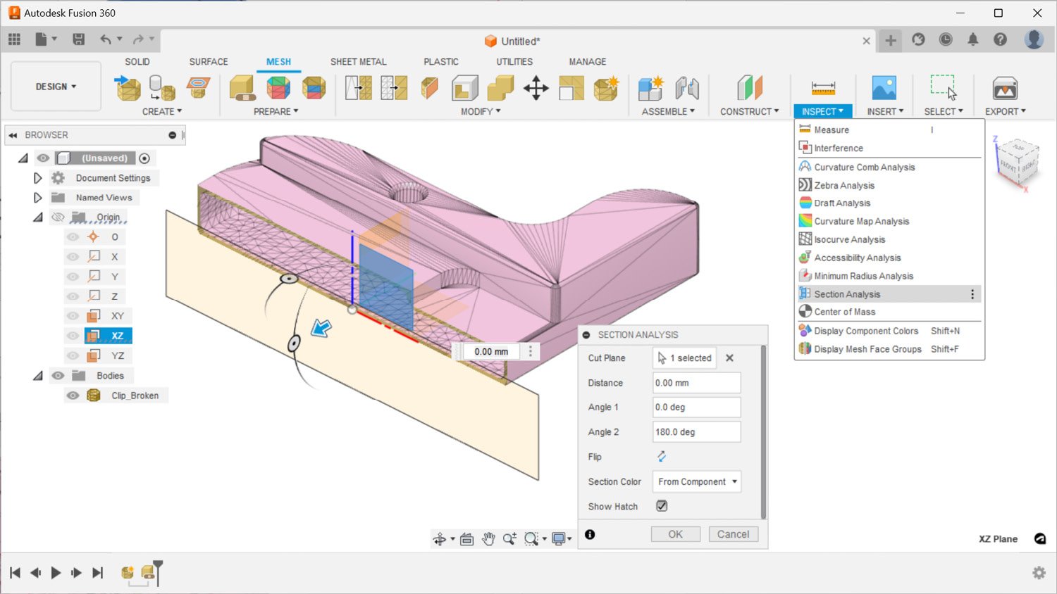
Figure 1.21 – A section analysis shows this mesh body is a hollow object
While the section analysis is visible, as denoted by the gray eye icon next to Section1 in the browser, we can edit our repair from the timeline and utilize the third repair type, called Wrap. This repair type makes the same repairs as Stitch and Remove and wraps the surface of the mesh body, removing all inner structures. As you can see in Figure 1.22, the outcome of this repair type removes the secondary shell inside our part, making our body a solid object. In this example, our goal was not to make such a drastic change to this part. Therefore, we will edit the repair one more time and move on to the fourth option. However, in some cases where the inner shell is also in need of major repair, this repair type could easily remove the triangles that belong to the inner shell, speeding up the mesh repair steps:
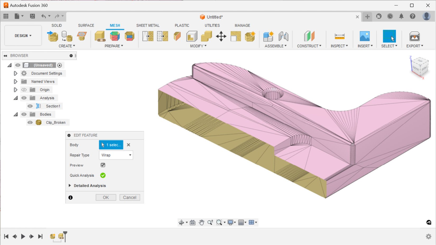
Figure 1.22 – The Wrap repair type and its impact on this part with a section analysis view
The fourth and final repair type is called Rebuild. There are multiple rebuild types available, and in Figure 1.23, you can see the outcome of a fast rebuild type with an average mesh density. This repair type reconstructs the mesh body and is the slowest repair type based on your density input. It can be used as a last resort when automatically repairing parts. However, the mesh outcome of this repair type has a high triangle count, and this repair type does a less desirable job of capturing details around sharp edges.
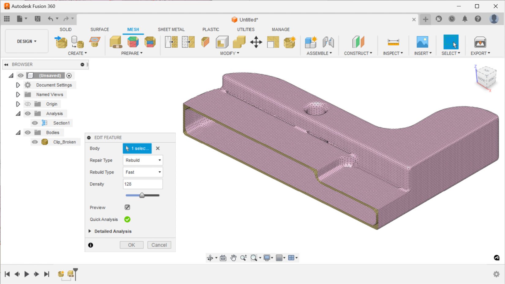
Figure 1.23 – The Rebuild repair type and its impact on this part with a section analysis view
Now that we have covered all four repair types, let’s edit a repair action, reuse the Stitch and Remove repair type, as its outcome was the most desirable for this part. This repair type also happens to be the default repair type recommended by Fusion.
None of the repair types were able to detect and repair the missing surface around the countersink hole. It looks like we will have to do some manual mesh editing actions to fix this issue. Let’s start by cutting the part in two, using the Plane Cut feature located in the MODIFY panel. The Clip_Broken mesh body is the body we will select to cut, and the cut plane will be the XZ plane. We will use the Trim type to remove the unwanted section and use the Minimal fill type to turn the remaining mesh body into a watertight object.
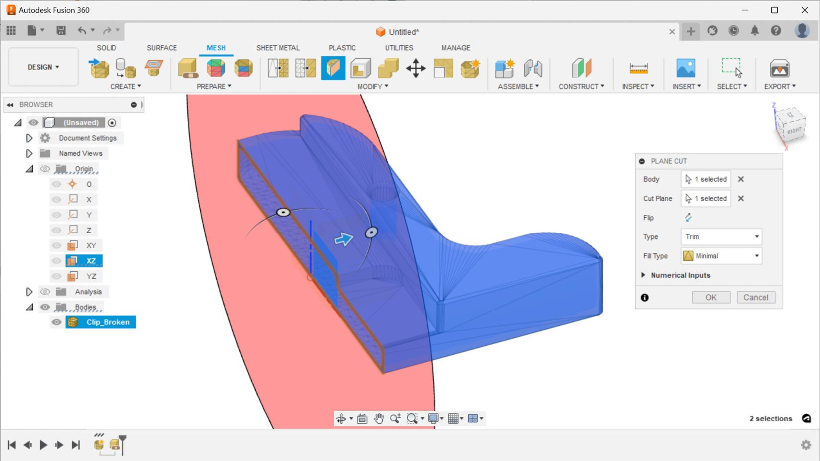
Figure 1.24 – Trimming the mesh body using the Plane Cut tool
Once we have cut the mesh body in half, we will have to create a component from the mesh body in order to mirror it. Figure 1.25 shows how to create a component from a trimmed mesh body – by right-clicking on it in the browser and selecting the Create Components from Bodies option.
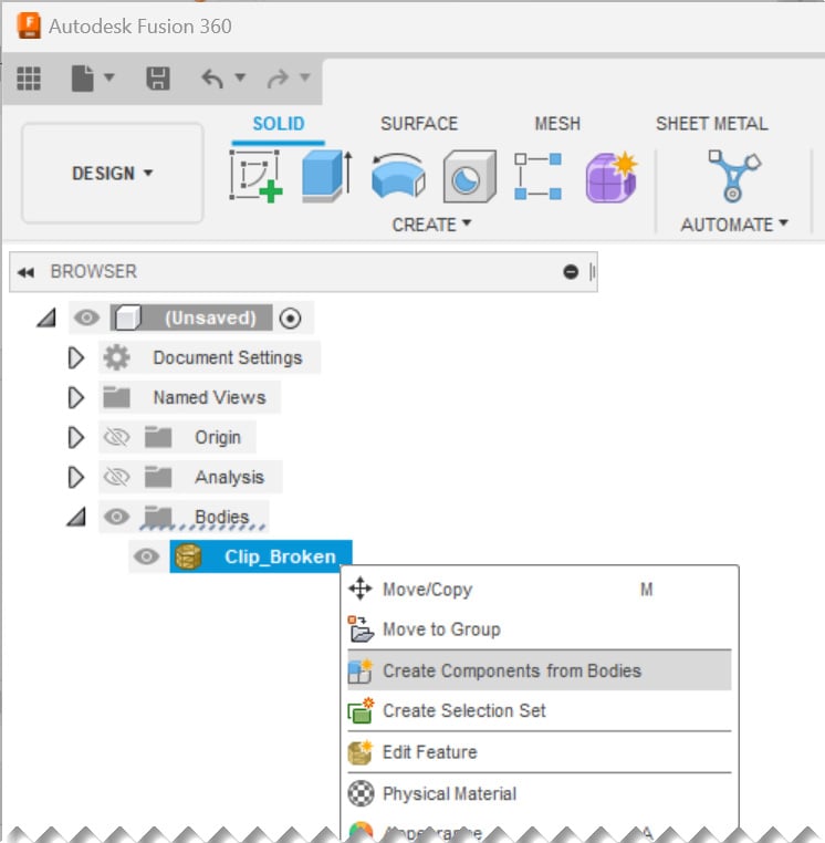
Figure 1.25 – Creating a new component from the trimmed mesh body
Once we have a component, we can toggle to the SOLID tab. We can select the Mirror command located under the CREATE panel. Once the MIRROR dialog is visible, we will have to change our object type to Components and select the newly created component to mirror. Our mirror plane will once again be the XZ plane. The outcome of the mirror action can be seen in Figure 1.26:
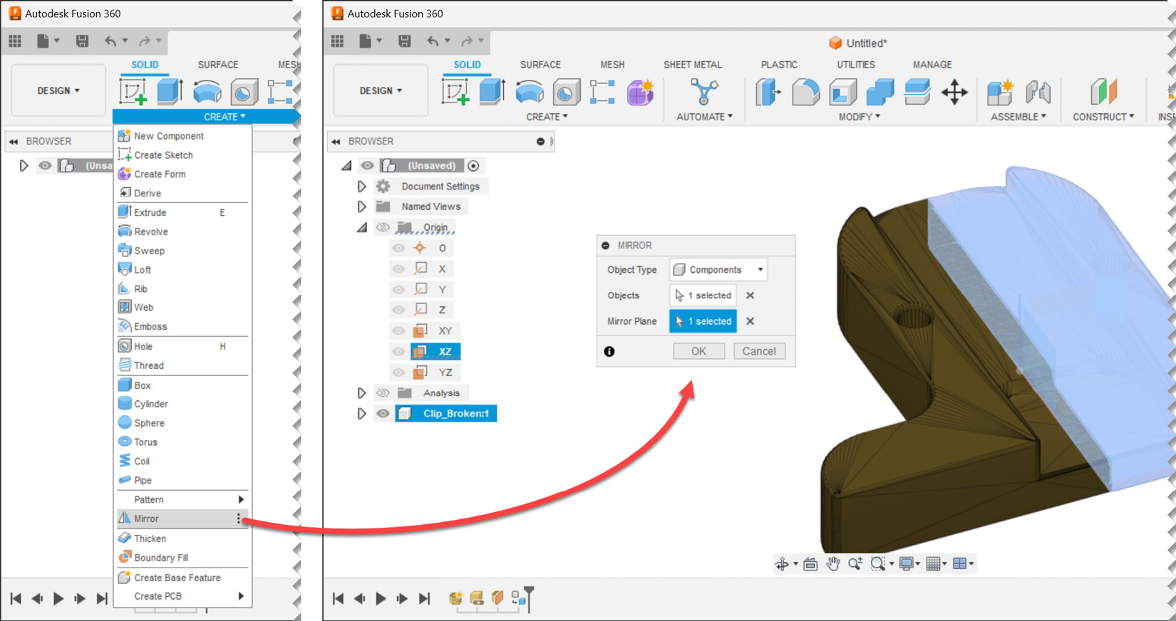
Figure 1.26 – Mirroring a component
After we mirror our component, we will end up with two mesh bodies within two components. It is time to combine them into a single unified component. To accomplish this, let’s go back to the MESH tab and utilize the combine command located within the MODIFY panel. We will have to select a target body and a tool body, which will be the Clip_Broken mesh bodies from the two components. We will utilize the join operation, create a new component, and keep the tools. This will ensure that we can easily compare the outcome and the input if desired in the future. Figure 1.27 shows the necessary input to combine two mesh bodies to make a new component:
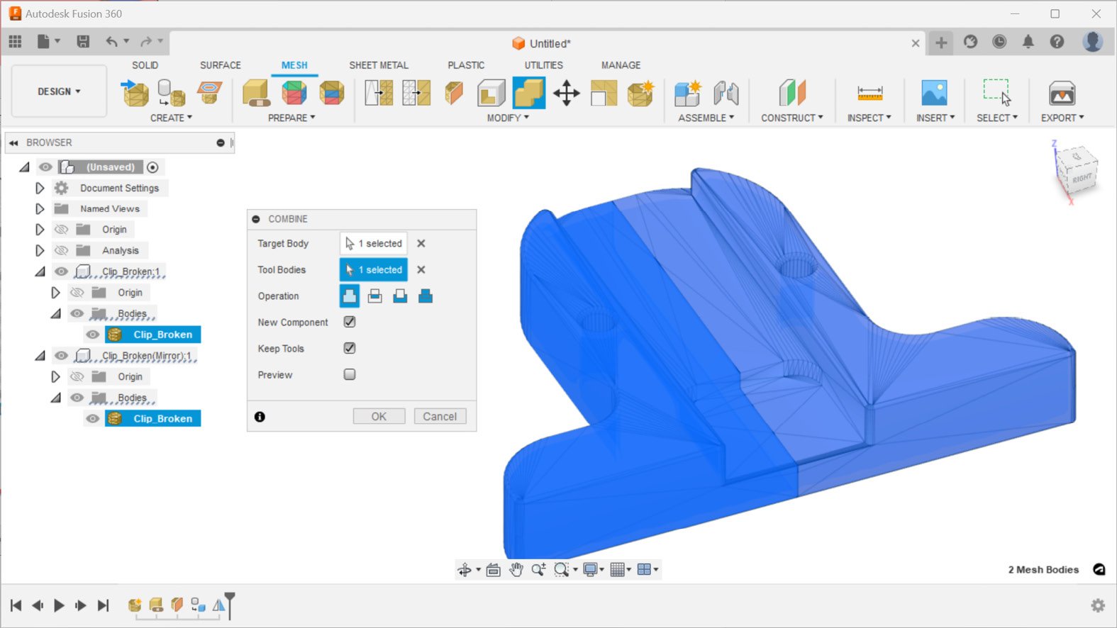
Figure 1.27 – Combining mesh bodies to make a new component
The outcome of the combined operation is a fully repaired body in a new component named Component3 in the browser. Figure 1.28 shows this new component while hiding the section analysis, as well as the first and second components:
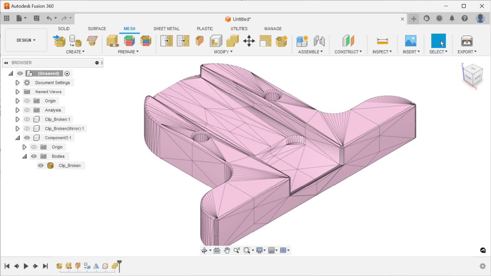
Figure 1.28 – Component3, a fully repaired mesh
If we turn on the visibility for the section analysis, we can quickly see that the mesh body we repaired still has a hollow cross-section and can be 3D-printed, as shown in Figure 1.29:
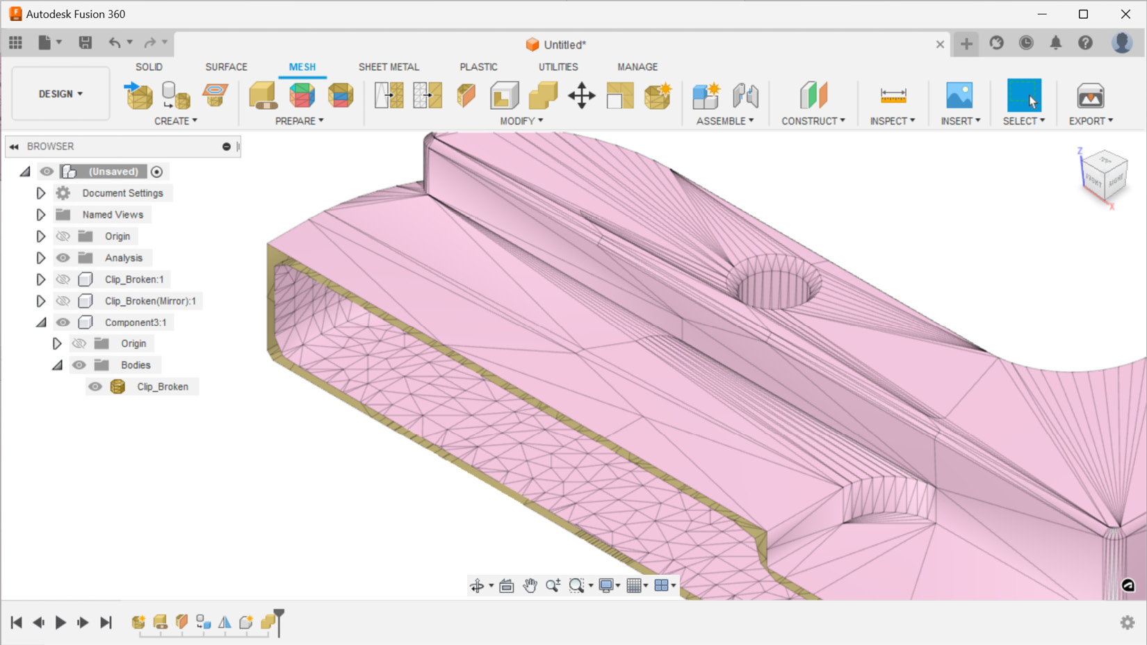
Figure 1.29 – A section analysis view of the repaired mesh body
As a final sanity check, it is always a good idea to look at the properties of the repaired mesh body to make sure we have a closed and oriented mesh with a positive volume. The timeline of all our actions is captured in the design history in the bottom-left corner of the browser, as shown in Figure 1.30. You can always replay those steps in the future and remind yourself how you were able to repair this mesh.
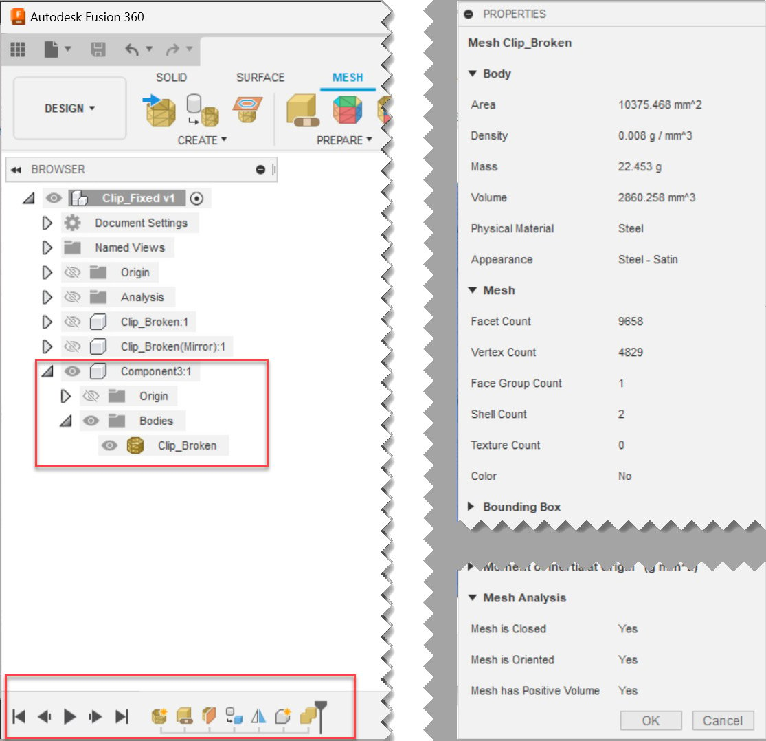
Figure 1.30 – The properties of repaired mesh and the repair actions timeline
The Git repository for this chapter also includes a Fusion file called Clip_fixed.f3d, which you can open directly in Fusion to replay the timeline if you had any issues during this example.


