Understanding SIS
The main goal of this chapter – and this book – is not to provide an extensive education on the engineering specifics of SISs, as many resources and publications already exist on this subject and have been available for some time. We will instead focus on what you need to understand about SISs within the context of cybersecurity, in order to allow you to grasp the ideas presented in this book without getting too caught up in the details.
SISs are deemed as the most critical barrier of plant process safety and the last prevention layer against process hazards. Usually, when combined with other engineering and administrative controls, a SIS provides a comprehensive set of safeguards and a layered protection approach as part of a plant’s safety philosophy to control risk to As Low As Reasonably Practicable (ALARP) or As Low As Reasonably Achievable (ALARA), taking into account social and economic factors. However, these measures are separate from those of a Basic Process Control System (BPCS), which is used for process control. This is the key differentiator between an SIS and a BPCS.
According to the International Electrotechnical Commission (IEC) definition, SISs are built to achieve three key objectives:
- To safely and gracefully (or partially) shut down a process when something goes wrong (i.e., a deviation from the norm)
- To let a process run when safe conditions are met
- To respond in a timely manner to prevent Emergency Shutdown (ESD), mitigate Fire and Gas (F&G), or minimize the consequences of a hazard
The term SIS typically consists of multiple elements. It includes, but is not limited to, sensors or detectors to monitor process conditions, logic solvers or controllers to process input signals, and final elements (such as valves or actuators) to perform operations and communication networks that facilitate the exchange of information. These components work together to ensure that the process remains within safe operating limits and to initiate an appropriate response when a safety-critical situation arises.
SIS elements
As depicted in the following illustration, an SIS consists of three key elements:

Figure 1.1 – SIS elements
Let’s discuss them further:
- Sensor: The sensors (or transmitters) are used to measure the process variable conditions and detect any hazardous conditions in the process.
Here are some common types of SIS sensors used in process industries:
- Pressure transmitters: Utilized to measure the pressure of gases or liquids in pipes or vessels
- Temperature transmitters: Employed to gauge the temperature of liquids or gases in vessels or pipes
- Level transmitters: Used to measure the level of liquid in tanks or vessels
- Flow transmitters: Widely deployed to measure the velocity of liquids or gases in pipes
- Gas detectors: Employed to ascertain the presence of hazardous gases in the environment, such as carbon monoxide and hydrogen sulfide
- Flame detectors: Used to detect the presence of flames, such as those caused by a fire
- Smoke detectors: Utilized to detect the presence of smoke, which can indicate the presence of a fire
- Motion sensors: Used to detect the movement of equipment or materials in a process, and can help to identify potential hazards or abnormal conditions
- Logic solver: The logic solver is essentially the CPU of the SIS that receives input signals, applies safety logic, and generates output signals to control devices such as valves and actuators. It processes data and makes decisions to ensure the safe operation of a process or industrial plant.
- Final element: The final element of an SIS is a physical device such as an on/off valve or actuator. It receives output signals from the logic solver and executes the necessary actions to maintain the safety of the plant.
A safety function is part of a system that can have several subsystems and elements:
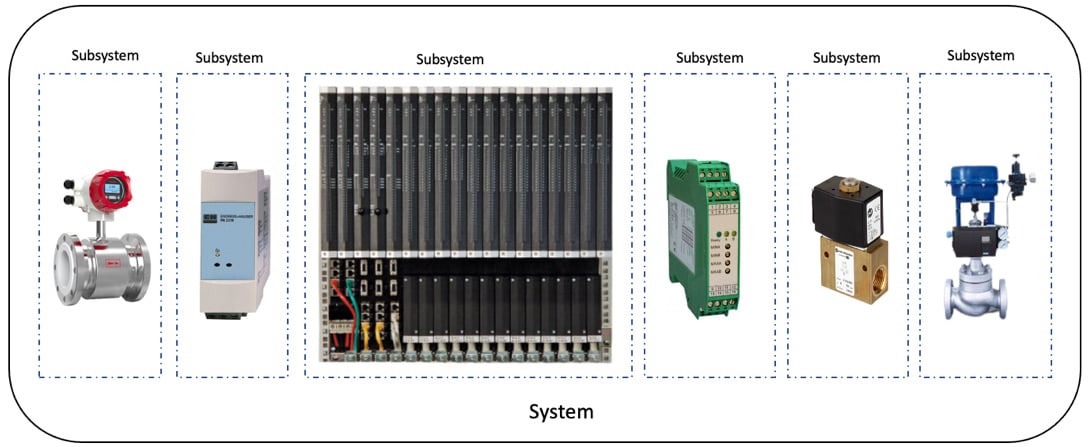
Figure 1.2 – Example of a system and subsystems
Like any complex system, an SIS can experience failures. There are several types of failures that can occur in an SIS, including the following:
- Random hardware failures: These are spontaneous failures at random times, which result from one or more possible degradation mechanisms in the hardware – for example, the aging of electronic components, mechanical failure of relays or solenoids, and so on.
- Software failures: SISs typically rely on software to perform complex calculations, monitor process data, and control final elements. Software failures can occur due to programming errors, memory leaks, or other issues.
- Systematic failures: These are when a pre-existing fault occurs under particular conditions and can only be eliminated by removing that fault by modification of the design, process, procedures, documentation, or other relevant factors.
Examples of systematic failures could be a hidden fault in the design or implementation of software as well as hardware, an error in the design specifications, user manuals, procedures or security operational procedures (SOPs), and so on. It can occur in any lifecycle phase activity.
- Configuration errors: SISs must be carefully configured to ensure that they perform their intended functions correctly. Configuration errors can occur due to human error, deviations or derogations, misinterpretation of specifications, or as a result of changes made to the system that are not properly tested.
- Environmental factors: SISs can be impacted by environmental factors such as temperature, humidity, and vibration. For example, extreme temperatures can cause electronic components to malfunction, and vibrations can cause wires or other connections to become loose.
- Cybersecurity threats: SISs are increasingly integrated with a BPCS, which increases their attack surface and makes them more susceptible to cyber risks. This can affect both process integrity and system availability.
An SIS can operate in four distinct states that are defined by the state I/O signals originating from the system, as presented in the following table:
|
SIS state |
Process status |
|
OK |
Process is available |
|
Safe |
Process has tripped |
|
Dangerous |
Process is available but not protected |
|
Intermediate |
Process is available and SIS is available, but it is time to repair it |
Table 1.1 – Different SIS states
Important note – deviations and derogations
Deviations typically refer to a departure from the standard performance or prescribed procedures of a system. In functional safety, for instance, a deviation could denote a failure in a safety function or system, resulting in the system not performing as intended. Such deviations could be due to individual component failures, system errors, or security weaknesses. Addressing these deviations necessitates investigating the root cause and devising corrective measures to bring the system back to its standard operating condition. In terms of cybersecurity, deviations could represent any unexpected or irregular activities that could potentially signify a breach or vulnerability threat that requires immediate investigation and remediation.
Derogations, on the other hand, represent a formal exemption from a standard or regulation. In the arena of ICS cybersecurity, derogations are often granted when it is impractical to adhere strictly to the standard or when alternative measures provide an equal or higher level of security. Typically, such derogations must be securely controlled, justified properly, and approved by relevant authority figures, ensuring they don’t compromise the overall integrity of the system. It’s important to note that derogations are not shortcuts or loopholes but are considered flexibilities within the regulatory framework, provided they don’t compromise the objective of the standard.
Both deviations and derogations hold immense significance for an ICS’s functional safety and cybersecurity. While managing deviations involves identifying, analyzing, and remediating unexpected occurrences, handling derogations involves ensuring any exemptions from standards maintain the requisite level of safety and security.
BPCS versus SIS
SISs are primarily designed to track and sustain the safety of the process and are typically passive and dormant for long periods of time. SISs wait to respond to system demands only when necessary. They use Safety Instrumented Functions (SIFs) to execute specific safety-related tasks such as Emergency Shutdown (ESD) and Fire and Gas (F&G).
Maintenance and diagnostics are essential in SISs to confirm that the system is functioning properly and reduce the need for manual tests. All SIS modifications after installation require strict compliance with the Management of Change (MoC) processes, as even the slightest alteration can have a significant impact.
On the other hand, BPCSs are very dynamic in nature with numerous changes. A BPCS provides oversight over the process with a range of digital and analog inputs and outputs that respond to logic functions, making it easier to detect any malfunctions or failures. However, these systems require frequent changes to ensure accurate process control. BPCSs typically consist of hardware and software components, including sensors, controllers, Human-Machine Interfaces (HMIs), and communication networks. BPCSs often use open standard protocols, such as Modbus and OPC, to communicate with other devices in the plant.
The following figure illustrates the typical components of BCPS and SIS and how they interact from a process perspective:
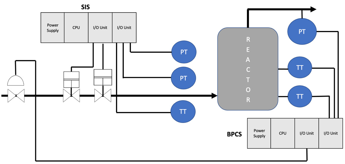
Figure 1.3 – BPCS versus SIS
SIS and BPCS have many similarities, yet their differences lead to different design, maintenance, and integrity requirements.
The implementation of cybersecurity for these systems varies significantly, yet both are susceptible to various threats, including malware, hacking, zero-days, Man-in-the-Middle (MitM) attacks, and human errors. Nevertheless, the ramifications of a successful SIS breach can be more severe than in BPCSs, as SISs are responsible for protecting the plant and its personnel from hazardous events. A compromised SIS can lead to the failure of safety functions and potentially catastrophic consequences, such as fires, explosions, and toxic releases. We will explore this further in the next chapter.
SIS applications – where are they used?
SISs are of paramount importance when it comes to protecting process safety. Process plants are beneficial as they can transform raw materials and ingredients into tangible products and goods as part of a complex supply chain. Unfortunately, the techniques used to conduct this conversion can trigger dangerous conditions that, if not efficiently controlled and properly contained, might cause major incidents or top events. Hazardous conditions may be present when dealing with combustible materials such as solids, liquids, gases, vapors, and dust.
In addition, administrative controls and safeguards should be used to address the control of risk.
SISs are deployed for many purposes in petrochemical facilities and pipelines and for other industry-specific needs. Examples of these systems include the following:
- ESD: This is a specialized form of control system, created to provide an extra layer of safety for high-risk areas such as oil and gas, nuclear power, and other potentially hazardous environments. Primarily, these systems serve to protect both personnel and the environment if process parameters exceed acceptable levels. By minimizing the potential damage from emergency scenarios such as uncontrolled flooding, the escape of hydrocarbons, and fire outbreaks, ESD systems provide an invaluable service.
The following screenshot presents an example of an ESD system and its components:
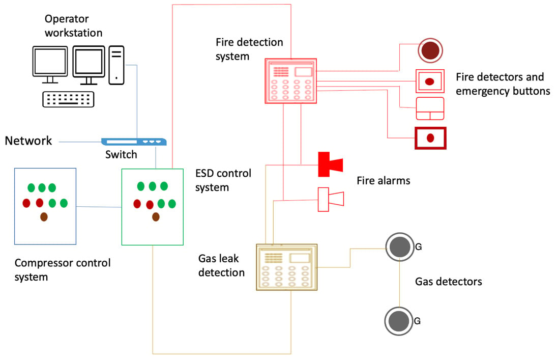
Figure 1.4 – ESD system
The main purpose of ESD can be summarized as follows:
- ESD systems detect unsafe conditions and initiate a shutdown of the process to prevent potentially hazardous situations.
- ESD systems are equipped with sensors that monitor process parameters such as pressure, temperature, level, and flow. If any of these parameters exceed a predetermined limit, the system will initiate a shutdown of the process.
- ESD systems can also be used to activate safety alarms or to stop certain components of the process. This ensures that safety is maintained and potential hazards are avoided.
- High-Integrity Protection Systems (HIPSs): HIPSs are deployed to prevent Process Shutdown (PSD) from being affected by any of the destructive factors of overpressure, elevated temperatures, and high-level events. The valves in the HIPS are closed decisively to make the production line secure, and one set of triggers records the observed processes, the logic solver (controller) processes the data, and a few end elements take the safeguarding action by cutting down or stopping the pumps with valves or actuated pumps and circuit breakers that perform the closing (shutdown) operation.
The HIPS serves as the ultimate protection system for the process, and often eliminates the need for pressure release, thereby tending to the environment and mitigating the risks linked to manual handling errors. It also calibrates the overconfidence (high level of trust) that engineers might sometimes have in Distributed Control Systems (DCSs) and ESD systems.
Some of the most popular deployments of HIPSs include, but are not restricted to, the following:
- High-integrity pressure protection systems
- High-integrity temperature protection systems
- High-integrity level protection systems
- HIPS interlock systems
The following illustration depicts a typical HIPS deployment for a subsea field environment:
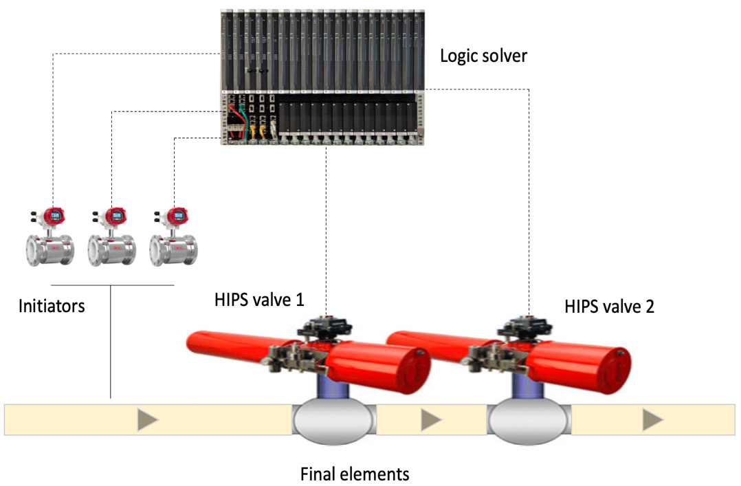
Figure 1.5 – HIPS
- Burner Management System (BMS): This is typically employed to ensure the safe ignition and operation as well as the shutdown of industrial burners when required. This system can be found in many process industries including oil and gas, power generation, manufacturing, and chemical industries, that rely on flame-operated equipment such as furnaces, boilers, and the like. The system is able to keep track of flames with flame detectors, as well as manage igniters, burners, and other actuators such as shut-off valves.
The majority of BMSs are designed with the aim of providing protection against potentially hazardous operating conditions and the admission of fuel that is not suitable. A BMS gives the user important status information and support, while additionally, if there is a hazardous condition, it can initiate a safe operating condition or a shutdown interlock.
According to the National Fire Protection Association (NFPA) 85 Boiler and Combustion Systems Hazards Code, a BMS is a control system that is devoted to boiler furnace safety and operator support. This system assures the safe and efficient working of the boiler, thereby contributing to the safety of the facility as a whole.
The chance of fire and hazards will increase significantly without a BMS in place. Organizations nowadays implement BMS in SIS to increase safety and system availability, as well as to remain compliant with sector regulations and the latest industry best practices.
Figure 1.6 illustrates an example of a BMS and its various elements:
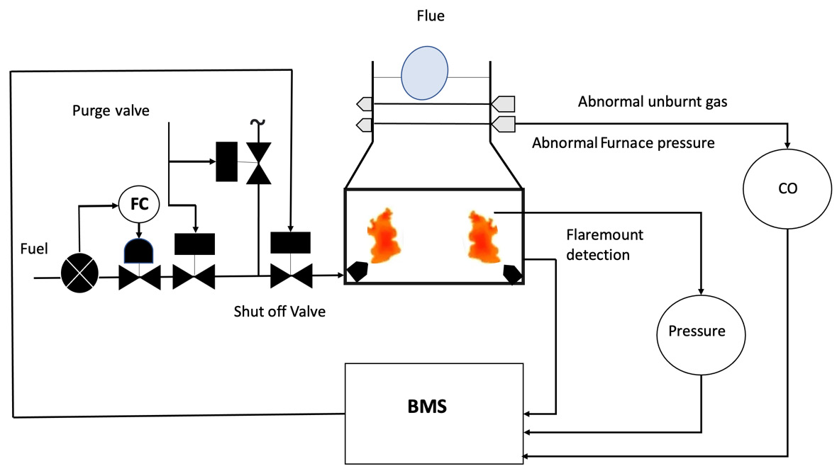
Figure 1.6 – BMS
A list of BMS components, including their functions, can be found in the following table:
|
Component |
Function |
|
Burner |
This is where a combination of fuel, oil, and/or gas is mixed with air and ignited to create heat. The process of combustion takes place in multiple burners of large heaters. |
|
FC (flow controller) |
This is used to monitor and control the fuel valves and ignitors of the BMS following a sequence that includes processes such as purging, ignition, operation, and shutdown. |
|
Flame detector |
This device is used to monitor the absence or presence of a flame and deploy a specific signal to detect it. |
|
Valves |
Their primary function is to control and shut off the flow of substances (oil, gas, etc.) into the fuel system. |
Table 1.2 – BMS components and functions
It is no surprise that SISs play an essential role within process industries in guaranteeing the safety and dependability of critical operations. A few examples of where an SIS is required to aid in the safeguarding of people, equipment, and the wider environment include the following:
- Process safety in the chemical industry: The use of SIS in the chemical industry can be focused on Health, Safety, and Environmental (HSE) considerations, and mitigating the consequences of a major accident. For example, an SIS can be used to automatically shut down a process if a critical parameter exceeds a predetermined limit, thereby preventing a catastrophic incident.
- Power generation: An SIS can be used in power generation plants to protect critical equipment and processes, such as turbines, boilers, and generators. For example, an SIS can be used to automatically shut down a turbine or generator in the event of an abnormal condition, such as low oil pressure or high temperature, to prevent damage to the equipment and ensure safe operation.
- Transportation safety: An SIS can be used in transportation systems, such as railways and pipelines, to detect and mitigate hazardous conditions. For example, an SIS can be used to automatically apply the brakes on a train if it exceeds a certain speed limit or if it encounters an obstacle on the track, thereby preventing a potential collision.
- Offshore oil and gas production: An SIS can be implemented in oil and gas environments – including oil fields and offshore platforms – to protect personnel as well as assets from the hazards of explosive gases, fire, and other risks associated with the production process. For example, an SIS can be used to automatically shut down production in the event of a leakage of gas or fire to prevent an explosion or other catastrophic event.
In the next section, we will examine ICS cybersecurity as a new discipline in detail. We will also explore how the IT and engineering communities perceive ICS cybersecurity in their respective fields.


