
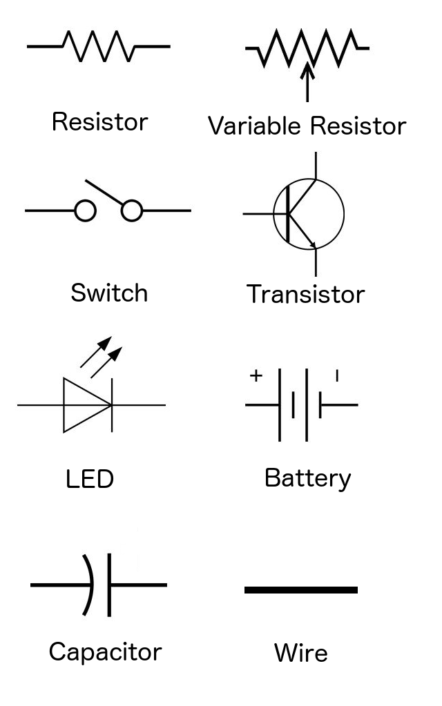
While the Fritzing diagrams used images to represent the circuit, schematic diagrams use symbols. This allows for a more compact diagram, which makes it easier to represent complex circuits. The following diagram shows the symbols for some of the more common electronic components in a schematic diagram:
We would use these symbols to represent the components in a circuit. To see what a schematic diagram would look like, let's create a simple circuit that contained a battery, resistor and LED. The Fritzing diagram for this circuit would look like this:
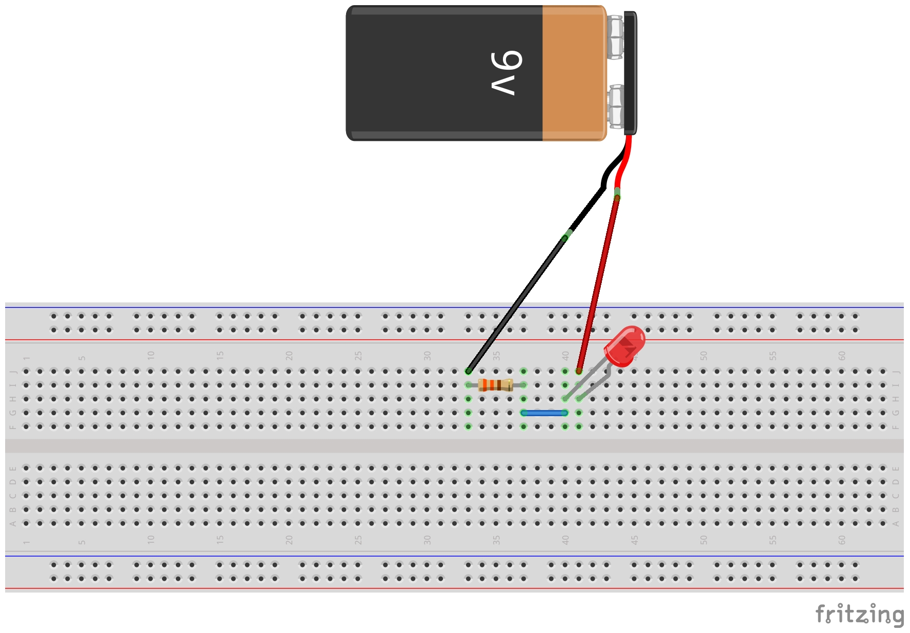
In this diagram, it is easy to see what components are needed and how they are connected; however, in more complex circuits it can be harder to see how everything is connected. The image from the Fritzing diagram also doesn't show the value of the components. A schematic diagram offers a much clearer...