
Lighting an LED when a button is pressed
Until now, we have only used code to directly control hardware components. Let's now try to read the state of a button in order to control an LED. We will need the following components:
- At least 6 jumper wires
- One LED (the color does not matter)
- One 220 Ohm resistor
- One 4-pinned-button (push down button)
- One 10K Ohm resistor
Now let's go on to build the circuit.
Building the circuit
The following circuit extends the one we previously built. So, if you still have the previous circuit assembled, you just have to add the button part. The next circuit consists of two component groups. The first group is used to control an LED, and the second group is used to read the button state.
Adding the LED component
We start off with the LED circuit:
- Place an LED with the cathode in G12 and the anode in G13.
- Use a 220 Ohm resistor to connect F13 with D13.
- Connect port D13 from the GPIO ports with A13 using a jumper wire.
- Connect F12 with the ground lane of the power bus using a jumper wire.
Adding the button component
Now we are going to add a button:
- Use a jumper wire to connect
A31with the positive lane of the power bus. - Use a 10K Ohm resistor to connect the ground lane of the power bus with
B29. - Connect
D29with portD2. - Place the push button with one pin in
E29, one inE31, one inF29, and the last pin inF31.
Our circuit should now look similar to the following:
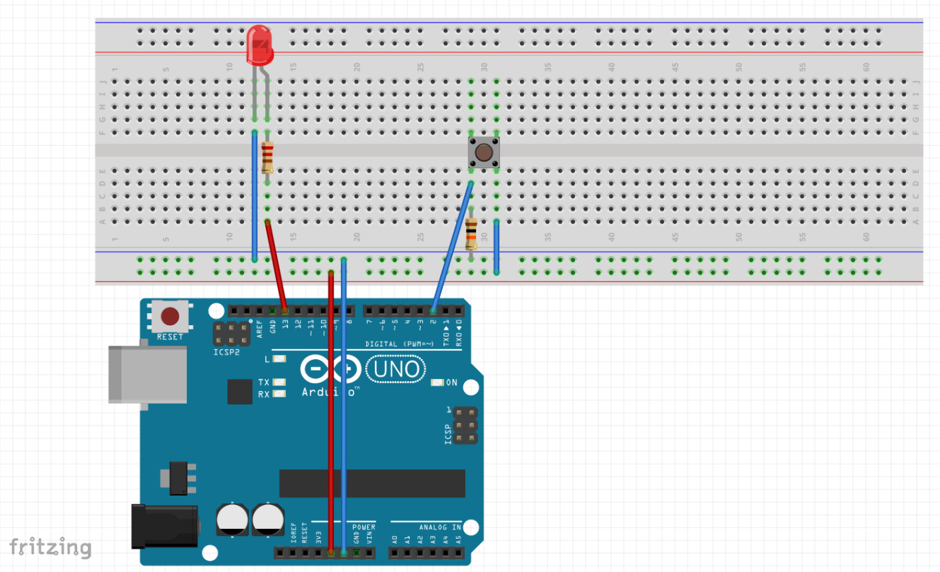
Figure 2.4 – The circuit – image taken from Fritzing
Note
Before we start to write the code for this circuit, we need to learn how these buttons work.
As the button will not work if you place it incorrectly onto the breadboard, let's have a look at the button again.
The 4 pins on the button are grouped into two pins each. So, two pins are connected to each other. Looking at the back of the button, we should be able to see that two opposing pins are connected to each other. So, the button won't work as expected when you place it rotated by 90°.
Programming the logic
Before diving into the code, we will create a new folder named light-button inside the Chapter02 folder and create a main.go file in it, with an empty main function, using the following:
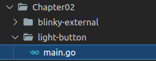
Figure 2.5 – The folder structure for the logic
Let's now look at the main function and the pull-up resistor.
The main function
We want to light the LED when the button is pressed. To achieve this, we need to read from a pin and check for its state using the following steps:
- Initialize the
outPutConfigvariable withPinConfiginPinOutputmode. This config is going to be used to control the LED pin:outputConfig := machine.PinConfig{Mode: machine. PinOutput} - Initialize the
inputConfigvariable withPinConfiginPinInputmode. This config is being used for the pin that reads the button state and therefore needs to be an input:inputConfig := machine.PinConfig{Mode: machine.PinInput} - Initialize the
ledvariable with a value ofmachine.D13, which is the pin we have connected toled:led := machine.D13
- Configure
ledas output by passingoutputConfigas the parameter, which is the pin that is connected to the button:led.Configure(outputConfig)
- Initialize the
buttonInputvariable with a value ofmachine.D2:buttonInput := machine.D2
- Configure
buttonInputas an input by passinginputConfigas the parameter:buttonInput.Configure(inputConfig)
- As we do not want the program to be terminated after checking the button state a single time, we use an endless loop to repeat and check forever:
for { - Check the current state of the button. It will be true if the button is pressed:
if buttonInput.Get() { - If the button is pressed, we light up the LED:
led.High()
- We are calling
continuehere, so we do not execute theled.Low()call:continue }
- If the button is not pressed, we turn the LED off:
    led.Low()
}
Note
Do not forget to import the
machinepackage, otherwise the code will not compile.
Now flash the program using the tinygo flash command:
tinygo flash –target=arduino Chapter02/light-button/main.go
After successfully flashing, the LED should light up when you press the button.
The pull-up resistor
You may have wondered why we need a 10K Ohm resistor in the button circuit. The 10K Ohm resistor is used to prevent the signal/pin from floating. Floating pins are bad, as an input pin in a floating state is indeterminate. When trying to read a value from a pin, we expect to get a digital value – 1 or 0, or true or false. Floating means that the value can change rapidly between 1 and 0, which happens without pull-up or pull-down resistors. Here's some further reading on floating pins: https://www.mouser.com/blog/dont-leave-your-pins-floating.
As an alternative to the 10K Ohm external resistor, an internal resistor can be used.
Configuring an input pin to use an internal resistor is done as follows:
inputConfig := machine.PinConfig{
               Mode: machine.PinInputPullup
}
We have now learned how to control an LED using an input signal, which was given by a button. The next step is to build the traffic lights flow to control three LEDs.