Configuring and controlling an RC car with Raspberry Pi
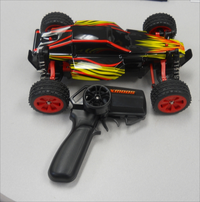
The first project that you'll be working on is a simple RC car, like the one shown here:

This particular car is an Xmods car, sold by Radio Shack, also available at other retail and online outlets. You can certainly use other RC cars as well. The advantage of this particular set is that the inputs to the drivetrain and steering are very easy to access.
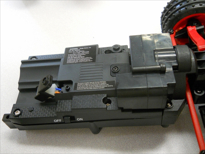
The following is the car, exposing the center control mechanism:

There are two connections that you will want direct access to. The first is the drive motor, and the second is the steering mechanism. For this particular model of RC car, the drive mechanism is in the rear. What you are normally looking for is two wires that will directly drive the DC motor of the car. On this system, there is a connector in the rear of the car, it looks as shown in the following image:

In the main control section of the car, you can see that there is a connector that plugs in these two wires in order to control the speed of the car, as shown here:

Remove this plug and these wires; you'll use Raspberry Pi and a motor controller to provide the voltage to the drive system of the car. The motor will run faster or slower based on the level of voltage that is applied to these wires and the polarity of the voltage will determine the direction. Raspberry Pi will need to provide a positive or negative 6 volt signal to control the speed and direction of the car.
You'll also need to replace the control signals that go to the front of the car for the steering. This is a bit more difficult. The following is the connector that goes to the front of the car:

The five-pin connector that comes from the control module is shown in the following:

The trick is to determine how the wires control the steering. One way to determine this is by opening up the unit, the following is how it looks from inside:

As you can see in the previous image, the blue and yellow wires are attached to a DC motor and the orange, brown, and red wires are attached to another control circuit. The motor will drive the wheels left or right, the polarity of the voltage will determine the direction, and its magnitude will cause the wheels to turn more or less sharply. The orange, brown, and red wires are interesting as their purpose is a bit difficult to discover. To do this, you can hook up a voltmeter and an oscilloscope. The orange and brown wires are straightforward, they are 3.5 volt and GND, respectively. The red wire is a control wire, the signal is a Pulse Width Modulation (PWM) signal, a square wave at 330 Hz and 10 percent duty cycle, and it is an enable control signal. Without the signal, the turning mechanism is not engaged.
Now that you understand the signals that are used in the original system to control the car, you can replicate those with Raspberry Pi. To control the steering, Raspberry Pi needs to provide a 3.3 volt DC signal, a GND signal, a 330 Hz, a 3.3 volt PWM signal, and the +/- 6 volt drive signal to the turning mechanism. To make these available, you can use the existing cables, solder some additional cable length, and use some shrink-wrap tubing to create a new connector with the connector that is available in the car:

You'll also need the access to the rear wheel compartment of your car to drive the two rear wheels. The following is how the access will look:

Also, you'll need to connect the battery power to Raspberry Pi, here is the modified connection to get the battery power from the car:

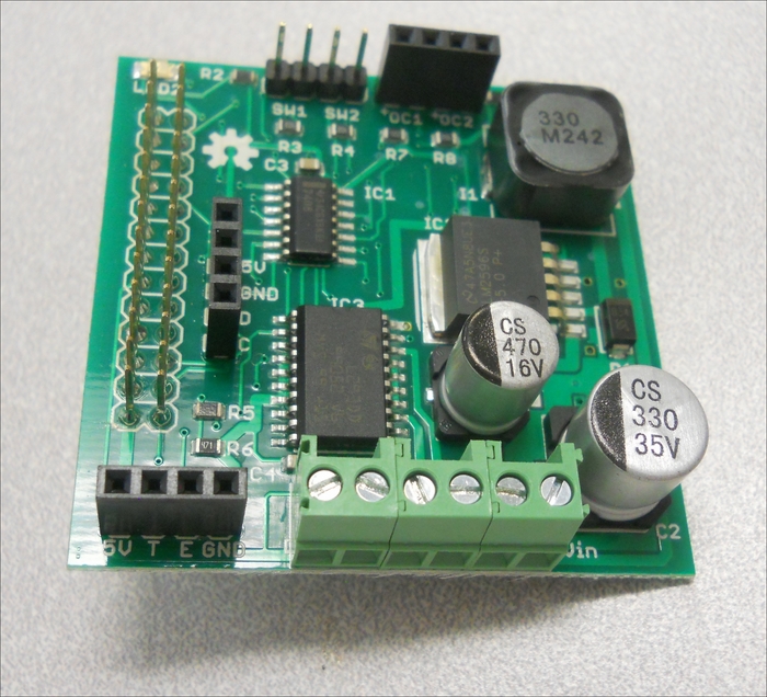
To control the car, you'll need to provide each of the control signals. The +/- 6 volt signals cannot be sourced directly by Raspberry Pi. You'll need some sort of motor controller to source the signal to control the rear wheel drive of the car and turning mechanism of the car. The simplest way to provide these signals is to use a motor shield, an additional piece of hardware that installs at the top of Raspberry Pi and can source the voltage and current to power both of these mechanisms. The RaspiRobot Board V2 is available online and can provide these signals. Here is a picture:

The specifics on the board can be found at http://www.monkmakes.com/?page_id=698. The board will provide two key signals to your RC car, the drive signal and the turn signal. You'll need one more additional signal, the PWM signal that enables the steering control. The following are the steps to connect Raspberry Pi to the board:
- First, connect the battery power connector to the power connector on the board, as shown in the following:

- Next, connect the rear drive signal to the motor 1 connectors on the board, similar to the following image:

- Connect the front drive connector to the motor 2 connectors on the board, as given in the following image:

- Connect the 3.3 volt and GND connectors to the General Purpose Input/Output (GPIO) pins of Raspberry Pi. Here is the layout of these pins:

- You'll use Pin 1 3.3V for the 3.3 volt signal and Pin 9 GND for the ground signal. You'll connect one of the GPIO pins so that you can create the 320 Hz, 10 percent duty cycle signal to enable the steering. Connect Pin 12 GPIO18, as shown in the following:

Now the hardware is connected.


