Sensing and actuating on IoT devices
In this section, we will learn how to sense and actuate on IoT devices. This part is important because we can gather data through sensor devices or interact with the environment through actuator devices. For testing, I use Arduino, from Arduino.cc, and Raspberry Pi boards.
Sensing and actuating on Arduino devices
Most Arduino development uses Sketch. This is a simple programming language for building Arduino applications. If you have experience in C/C++, you'll be familiar with the programming syntax.
To start your development, you can download Arduino software from https://www.arduino.cc/en/Main/Software. After that, read about Arduino API at http://www.arduino.cc/en/Reference/HomePage.

Related to digital and analog I/O, you should be familiar with the following Sketch API:
digitalRead()reads data from a digital pin on ArduinodigitalWrite()writes data to a digital pin on ArduinoanalogRead()reads analog data from an analog pin on ArduinoanalogWrite()writes analog data to an analog pin on Arduino
In this section, I'll show you how to work with analog and digital I/O on Arduino. I use a light sensor. LDR or Photoresistor sensors are low-priced light sensor device. Even Seeedstudio has already designed one in module form, Grove – Light Sensor(P). You can review it at http://www.seeedstudio.com/depot/Grove-Light-SensorP-p-1253.html. This module has four pins, but you only connect the VCC and GND pins to the VCC and GND pins of your Arduino board. Then, the SIG pin is connected to an analog pin of the Arduino board. The following figure shows a Grove – Light Sensor(P):
You will need the following resources for testing:
- Jumper cables
- Light sensor module, http://www.seeedstudio.com/depot/Grove-Light-SensorP-p-1253.html
Now you can connect digital 6 to digital 7. Then, the SIG pin from the LDR module is connected to A0. The VCC and GND pins of the LDR module are connected to 3V3 and GND. You can see the hardware wiring in the following figure:

This wiring is built using Fritzing, http://fritzing.org. It's available for Windows, Linux, and Mac. You can build your own wiring with some electronics components and boards. This tool provides a lot of electronics components. You can also add your own electronics components or downloads from the Internet.
My wiring implementation is shown in the following figure:

The next step is to write an Arduino program. Open your Arduino software, then, write the following program:
int dig_output = 7;
int dig_input = 6;
int analog_input = A0;

int digital_val = LOW;

void setup() {
  Serial.begin(9600);

  pinMode(dig_output, OUTPUT);
  pinMode(dig_input, INPUT);
}

void loop() {

  digitalWrite(dig_output,digital_val);
  int read_digital = digitalRead(dig_input);
  Serial.print("Digital write: ");
  Serial.print(digital_val);
  Serial.print(" read: ");
  Serial.println(read_digital);

  int ldr = analogRead(analog_input);
  Serial.print("Analog read: ");
  Serial.println(ldr);

  if(digital_val==LOW)
    digital_val = HIGH;
  else
    digital_val = LOW;

  delay(1000);
}
Save this program as ArduinoIO. You can deploy this program to your Arduino board through Arduino software.
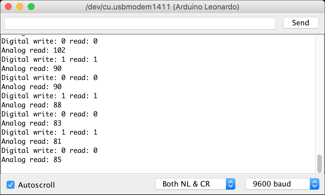
When finished, you can open the Serial Monitor tool from your Arduino software:

This program sends digital data (high and low values) from digital pin 7 to digital pin 6. You can read a light value from the LDR module via analogRead() on the A0 pin.
For the second sensing testing scenario, we will try to read temperature and humidity data from a sensor device. I use DHT-22. The RHT03 (also known as DHT-22) is a low-cost humidity and temperature sensor with a single wire digital interface. You can obtain this module from SparkFun, https://www.sparkfun.com/products/10167, and Adafruit, https://www.adafruit.com/products/393. You could also find this module in your local electronics store or online.

DHT22 module. Source: https://www.adafruit.com/products/385
Further information about the DHT-22 module, you can read the DHT-22 datasheet at http://cdn.sparkfun.com/datasheets/Sensors/Weather/RHT03.pdf.
Now we connect DHT-22 module to Arduino. The following is the wiring:
- VDD (pin 1) is connected to the V3V pin on Arduino
- SIG (pin 2) is connected to digital pin 8 on Arduino
- GND (pin 4) is connected to GND on Arduino
You can see this wiring in the following figure:

You can see my wiring implementation in the following figure:

To access DHT-22 on Arduino, we can use the DHT Sensor library from Adafruit, https://github.com/adafruit/DHT-sensor-library. We can install this library from the Arduino software. Click the menu Sketch | Include Library | Manage Libraries so you will get a dialog.
Search dht in
Library Manager. You should see the DHT sensor library by Adafruit. Install this library:

When installation is complete, you can start to write programs on the Arduino software. The following is a program sample for reading temperature and humidity from the DHT-22 module:
#include "DHT.h"

// define DHT22
#define DHTTYPE DHT22
// define pin on DHT22
#define DHTPIN 8

DHT dht(DHTPIN, DHTTYPE);

void setup() {
  Serial.begin(9600);
  dht.begin();
}

void loop() {
  delay(2000);

  // Reading temperature or humidity takes about 250 milliseconds!
  // Sensor readings may also be up to 2 seconds 'old' (its a very slow sensor)
  float h = dht.readHumidity();
  // Read temperature as Celsius (the default)
  float t = dht.readTemperature();


  // Check if any reads failed and exit early (to try again).
  if (isnan(h) || isnan(t)) {
    Serial.println("Failed to read from DHT sensor!");
    return;
  }

  // Compute heat index in Celsius (isFahreheit = false)
  float hic = dht.computeHeatIndex(t, h, false);

  Serial.print("Humidity: ");
  Serial.print(h);
  Serial.print(" %\t");
  Serial.print("Temperature: ");
  Serial.print(t);
  Serial.print(" *C\t");
  Serial.print("Heat index: ");
  Serial.print(hic);
  Serial.println(" *C ");
}
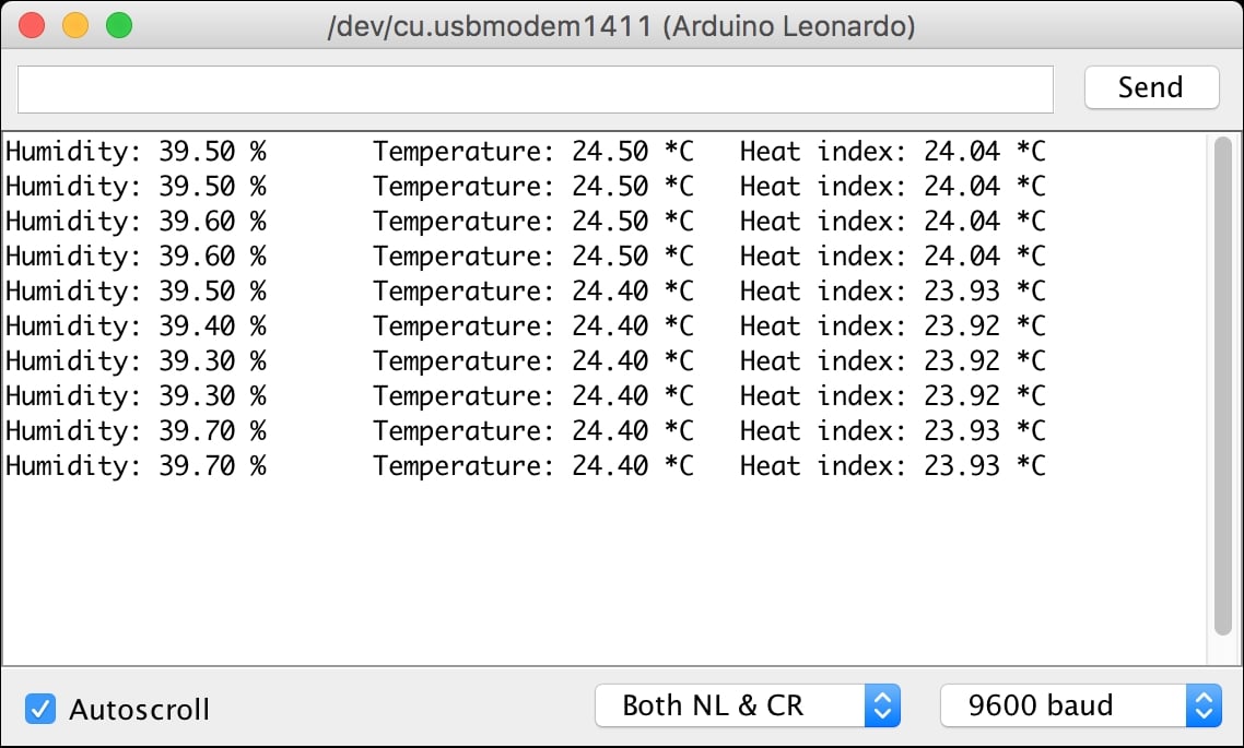
Save this program as ArduinoDHT. Now you can compile and upload the program to your Arduino board. After that, open Serial Monitor to see the temperature and humidity data:

How does it work?
In the setup() function, we initialize the DHT module by calling dht.begin(). To read temperature and humidity, you can use dht.readTemperature() and dht.readHumidity(). You also can get a heat index using the dht.computeHeatIndex() function.
Sensing and actuating on Raspberry Pi devices
Raspberry Pi board is one of boards used for testing experiments in this book. In this section, we use Raspberry Pi to sense and actuate with external devices. I use a Raspberry Pi 3 board for testing.
Setting up
Before you use a Raspberry Pi board, you need to set up an OS on the board. OS software can be deployed on a microSD card. It's recommended to use an 8-GB microSD card . There's a lot of OS software you can use on a Raspberry Pi board. You can check it out at https://www.raspberrypi.org/downloads/.
For testing purposes, I use Raspbian, https://www.raspberrypi.org/downloads/raspbian/, as the OS on my Raspberry Pi board. Raspbian is an operating system, based on Debian, optimized for Raspberry Pi. Follow the installation guidelines at https://www.raspberrypi.org/documentation/installation/installing-images/README.md. Raspbian is just one OS for Raspberry Pi OS. You can try other Raspberry Pi OSes at https://www.raspberrypi.org/downloads/.
Accessing Raspberry Pi GPIO
If you use the latest version of Raspbian (Jessie or later), wiringPi module, http://wiringpi.com, is already installed for you. You can verify your wiringPi version on Raspberry Pi Terminal using the following command:
$ gpio -v
You should see your wiringPi module version. A sample of the program output can be seen in the following screenshot:

Furthermore, you can verify the Raspberry GPIO layout using the following command:
$ gpio - readall
This command will display the Raspberry Pi layout. It can detect your Raspberry Pi model. A sample of the program output for my board, Raspberry Pi 3, can be seen in the following screenshot:

For Raspberry Pi GPIO development, the latest Raspbian also has the RPi.GPIO library already installed—https://pypi.python.org/pypi/RPi.GPIO, for Python, so we can use it directly now.
To test Raspberry Pi GPIO, we put an LED on GPIO11 (BCM 17). You can see the wiring in the following figure:

Now you can write a Python program with your own editor. Write the following program:
import RPi.GPIO as GPIO
import time


led_pin = 17
GPIO.setmode(GPIO.BCM)
GPIO.setup(led_pin, GPIO.OUT)


try:
    while 1:
        print("turn on led")
        GPIO.output(led_pin, GPIO.HIGH)
        time.sleep(2)
        print("turn off led")
        GPIO.output(led_pin, GPIO.LOW)
        time.sleep(2)

except KeyboardInterrupt:
    GPIO.output(led_pin, GPIO.LOW)
    GPIO.cleanup()


print("done")
The following is an explanation of the code:
- We set GPIO type using
GPIO.setmode(GPIO.BCM). I used theGPIO.BCMmode. In GPIO BCM, you should see GPIO values on the BCM column from the GPIO layout. - We defined GPIO, which will be used by calling
GPIO.setup()as the output mode. - To set digital output, we can call
GPIO.output().GPIO.HIGHis used to send 1 to the digital output. Otherwise,GPIO.LOWis used for sending 0 to the digital output.
Save this program into a file called ch01_led.py.
Now you can run the program by typing the following command on your Raspberry Pi Terminal.
$ sudo python ch01_led.py
We execute the program using sudo, due to security permissions. To access the Raspberry Pi hardware I/O, we need local administrator privileges.
You should see a blinking LED and also get a response from the program. A sample of the program output can be seen in the following screenshot:

Sensing through sensor devices
In this section, we will explore how to sense from Raspberry Pi. We use DHT-22 to collect temperature and humidity readings on its environment.
To access DHT-22 using Python, we use the Adafruit Python DHT Sensor library. You can review this module at https://github.com/adafruit/Adafruit_Python_DHT.
You need required libraries to build Adafruit Python DHT Sensor library. Type the following commands in your Raspberry Pi Terminal:
$ sudo apt-get update
$ sudo apt-get install build-essential python-dev
Now you can download and install the Adafruit Python DHT Sensor library:
$ git clone https://github.com/adafruit/Adafruit_Python_DHT
$ cd Adafruit_Python_DHT/
$ sudo python setup.py install
If finished, we can start to build our wiring. Connect the DHT-22 module to the following connections:
- DHT-22 pin 1 (VDD) is connected to the 3.3V pin on your Raspberry Pi
- DHT-22 pin 2 (SIG) is connected to the GPIO23 (see the BCM column) pin on your Raspberry Pi
- DHT-22 pin 4 (GND) is connected to the GND pin on your Raspberry Pi
The complete wiring is shown in the following figure:

The next step is to write a Python program. You can write the following code:
import Adafruit_DHT
import time

sensor = Adafruit_DHT.DHT22

# DHT22 pin on Raspberry Pi
pin = 23


try:
    while 1:
        print("reading DHT22...")
        humidity, temperature = Adafruit_DHT.read_retry(sensor, pin)

        if humidity is not None and temperature is not None:
            print('Temp={0:0.1f}*C  Humidity={1:0.1f}%'.format(temperature, humidity))

        time.sleep(2)

except KeyboardInterrupt:
    print("exit")


print("done")
Save this program into a file called ch01_dht22.py. Then, you can run this file on your Raspberry Pi Terminal. Type the following command:
$ sudo python ch01_dht22.py
A sample of the program output can be seen in the following screenshot:

How does it work?
First, we set our DHT module type by calling the Adafruit_DHT.DHT22 object. Set which DHT-22 pin is attached to your Raspberry Pi board. In this case, I use GPIO23 (BCM).
To obtain temperature and humidity sensor data, we call Adafruit_DHT.read_retry(sensor, pin). To make sure the returning values are not NULL, we validate them using conditional-if.


