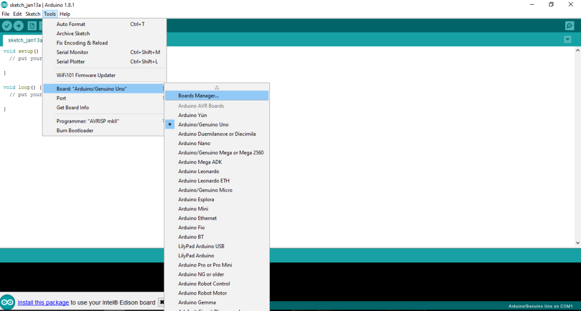
The Arduino IDE is a famous, and widely used, integrated developer environment that not only covers Arduino boards but also many other boards of Intel including Galileo, Edison, Node MCU, and so on. The language is based on C/C++. Once you download the Arduino IDE from the link mentioned at the beginning of this chapter, you may not receive the Edison board package. We need to manually download the package from the IDE itself. To do that, open up your Arduino IDE, and then go to Tools | Board: "Arduino/Genuino Uno" | Board Manager...:

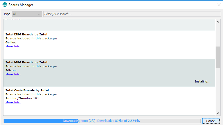
You now need to click on Boards Manager and select Intel i686 Boards. Click on the version number and then click on Install. Boards Manager is an extremely important component of the IDE. We use the Boards Manager to add external Arduino-compatible boards:

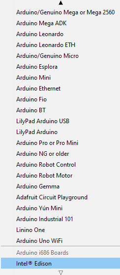
Once installed, you should see your board displayed under Tools Boards:

Once successfully installed, you will now be able to program the device using the IDE. Like every starter program, we'll also be burning a simple program into the Intel Edison which will blink the on-board LED at certain intervals set by us. Through this, the basic structure of the program using the Arduino IDE will also be clear. When we initially open the IDE, we get two functions:
- void setup()
- void loop()
The setup function is the place where we declare whether the pins are to be configured in output mode or input mode. We also start various other services, such as serial port communication, in the setup method. Depending on the usecase, the implementation changes. The loop method is that segment of the code that executes repeatedly in an infinite sequence. Our main logic goes in here. Now we need to blink an LED with an interval of 1 second:
#define LED_PIN 13
void setup()
  {
    pinMode(LED_PIN, OUTPUT);
  }

void loop()
  {
    digitalWrite(LED_PIN, HIGH);
    delay(1000);
    digitalWrite(LED_PIN, LOW);
    delay(1000);
  }
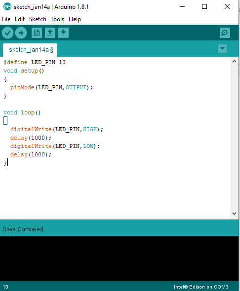
In the preceding code, the line #define LED_PIN 13 is a macro for defining the LED pin. In the Arduino expansion board, an LED and a resistor is already attached to pin 13, so we do not need to attach any additional LEDs for now. In the setup function, we have defined the configuration of the pin as output using the pinMode function with two parameters. In the loop function, we have initially set the pin to high by using the digitalWrite function with two parameters, and then we've defined a delay of 1,000 miliseconds which is equivalent of 1 second. After the delay, we set the pin to low and then again define a delay of 1 second. The preceding code explains the basic structure of the Arduino code written in the Arduino IDE.
To burn this program to the Edison device, first compile the code using the compile button, then select the port number of your device, and finally click the Upload button to upload the code:

The port number can be selected under Tools | port.
Now that we know how to program using an Arduino, let's have a look at how it actually works or what's happening inside the Arduino IDE.
A number of steps actually happen while uploading the code:
- First, the Arduino environment performs some small transformations to make sure that the code is correct C or C++ (two common programming languages).
- It then gets passed to a compiler (avr-gcc), which turns the human readable code into machine readable instructions (or object files).
- Then, your code gets combined with (linked against), the standard Arduino libraries that provide basic functions such as digitalWrite() or Serial.print(). The result is a single Intel hex file, which contains the specific bytes that need to be written to the program memory of the chip on the Arduino board.
- This file is then uploaded to the board, transmitted over the USB or serial connection via the bootloader already on the chip or with external programming hardware.


