


Arduino boards
Arduino was originally created for artists and designers as an easy and quick prototyping tool. Designers were able to create sophisticated designs and artworks even without having knowledge of electronics and programming. So it is understood that the first few steps of learning Arduino are very easy. In this section, you will get introduced to different Arduino boards and learn how to choose an Arduino board for your project and some information on the Arduino UNO board, which you will be using throughout this book.
Different Arduino boards
Beginners often get confused when they discover Arduino projects. When looking for Arduino, they hear and read such terms as Uno, Zero, and Lilypad. The thing is, there is no such thing as "Arduino". In 2006, the Arduino team designed and developed a microcontroller board and released it under an open source license. Over the years, the team has improved upon the design and released several versions of the boards. These versions mostly had Italian names. There are numbers of boards that the team has designed over the past 10 years:
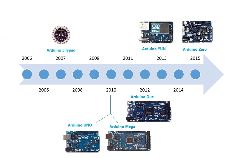
The Arduino team didn't just improve on design, they invented new designs for specific use cases in mind. For example, they developed Arduino Lilypad to embed a board into textiles. It can be used to build interactive T-shirts. The following table shows the capability of different Arduino boards. Arduino boards may differ in their appearance, but they have a lot in common. You can use the same tools and libraries to program:
|
Name |
Processor |
Dimension |
Voltage |
Flash(kB) |
Digital I/O(PWM) pins |
Analog input pins |
|---|---|---|---|---|---|---|
|
Arduino Lilypad |
ATmega168V |
51 mm outer diameter |
2.7-5.5 V |
16 |
14(6) |
6 |
|
Arduino YUN |
Atmega32U4 |
68.6 mm × 53.3 mm |
5 V |
32 |
14(6) |
12 |
|
Arduino Mega |
ATmega2560 |
101.6 mm × 53.3 mm |
5 V |
256 |
54(15) |
16 |
|
Arduino Due |
ATSAM3X8E |
101.6 mm × 53.3 mm |
3.3 V |
512 |
54(12) |
12 |
|
Arduino Zero |
ATSAMD21G18A |
68.6 mm × 53.3 mm |
3.3 V |
256 |
14(12) |
6 |
|
Arduino UNO |
ATmega328P |
68.6 mm × 53.3 mm |
5 V |
32 |
14(6) |
6 |
As Arduino boards' design and schematics are open source, anyone can use and change the original board design and can create their own version of an Arduino-compatible board. Because of that, you can find countless Arduino clones on the web which can be programmed using the same tools and libraries used for original Arduino boards.
How to choose an Arduino board for your project
With so many options available, it becomes challenging for a person to decide which Arduino board to use for a project. The Arduino family is huge, and it is impossible to read about each and every board and decide upon which board to use for a particular project.
The following flowchart simplifies the process by providing a decision tree for widely-used Arduino boards and the most common use cases/applications:
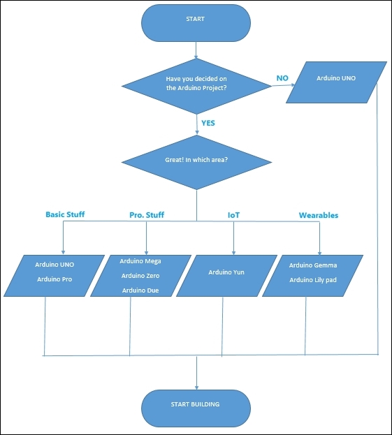
If you are not sure what you will build and what hardware capabilities are required, start building your prototype using Arduino UNO. Arduino UNO has the best documentation and best support. It is also the most compatible of all Arduino boards. Most of the existing libraries and shields are compatible with Arduino UNO. And finally, most of the code that has been written on earlier versions of Arduino boards will also work with Arduino UNO.
Note
Arduino shields are modular circuit boards that can be plugged on top of the Arduino PCB, extending its capabilities. Want to connect your Arduino to the Internet? There is a shield for that. There are hundreds of shields available online, which makes Arduino more than just a development board.
Throughout this book, we will use the Arduino UNO board.
Arduino UNO
"UNO" means one in Italian, and it was chosen to mark the release of Arduino IDE v1.0. It is the first in a series of USB Arduino boards. As mentioned before, it is one of the most widely used boards in the Arduino Family:
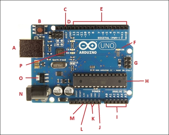
In this section you will get introduced to different components of the Arduino UNO board.
A: USB plug: Every Arduino board needs a way to be connected to a power source. The Arduino UNO can be powered from a USB cable coming from your computer. The USB connection is also how you will load code onto your Arduino board.
B: Reset button: Pushing it will temporarily connect the reset pin to ground and restart any code that is loaded on the Arduino board.
C: ARE F: This stands for Analog Reference. In this book, you are not going to use this pin. It is sometimes used to set an external reference voltage (between 0 and 5) as the upper limit for the analog input pins.
D: GND: Digital ground.
E: Pin 0 to Pin 13: The area of pins under the DIGITAL label are digital pins. These pins can be used for both digital input (like telling if a button is pushed) and digital output (like powering an LED). Next to some of the pins (3, 5, 6, 9, 10, and 11) there is a tilde (~) sign, which means those pins can also act as pulse width modulation apart from normal digital pins. PWM (pulse width modulation) is a technique for getting an analogue signal with digital means by controlling on and off duration of the signal.
F: ON: This is a power LED indicator. This LED should light up whenever you plug your Arduino into a power source. If the LED doesn't turn ON, there is something wrong with your Arduino board.
G: In-circuit serial programmer: You will use these pins very rarely. Mostly, hardware manufacturers use these pins for debugging purposes. Also, these pins are used to program Arduino using other Arduino or other microcontrollers.
H: Main IC: This is an ATmega 328 microcontroller. Think of it as the brain of your Arduino board.
I: Pin A0 to Pin A5: The area of pins under the Analog In label are Analog In pins. These pins can read the signal from an analog sensor (like a temperature sensor) and convert it into a digital value that can be read by Arduino software and can be used for further processing.
J: Vin: Voltage In. Arduino can be supplied with power from a DC jack, the USB connector, or Vin pin. While supplying with Vin, you can give up to 12 V. The in-built regulator in Arduino will take care of regulating voltage to 5 V.
K: GND: Ground pin.
L: 5 V: Power pin which supplies 5 volts.
M: 3.3 V: Power pin which supplies 3.3 volts.
N: External power supply: Once you have uploaded your code to Arduino you don't need a computer just to draw power. You can use an external power supply and can use Arduino as a standalone device.
O: Voltage regulator: The voltage regulator is not actually something you can interact with on Arduino. It controls the amount of voltage that is let into the Arduino board.
P: Tx Rx LEDs: Tx is short for transmit, RX is short for receive. In electronics, TxRX are used to indicate the pins responsible for serial communication. These LEDs will give nice visual indications whenever our Arduino is receiving or transmitting data.


