Building the robot arm
You are now ready to build the robot arm that will be controlled by Intelligent Hub. In order to achieve this, you will need to take the following steps:
- Start with four black connector pins and add them to the front yellow base plate, as shown in Figure 2.24:

Figure 2.24 – Placement of the black connector pins
- On top of these four black connector pins, add the large motor from the kit, as shown in Figure 2.25:

Figure 2.25 – Attach the large motor to the black connector pins
- Once your motor is secure to the yellow base plate, add two blue connector pins and one black biscuit to the motor. The blue connector pins will be placed on the top and bottom pin holes of the motor, not the right and left sides.

Figure 2.26 – Attach the blue connector pins and biscuit
Be sure your motor is aligned to position 0 (gray dots aligning):

Figure 2.27 – Motor aligned to position 0
- On top of the black biscuit element using the blue connector pins, you will add a medium motor facing to the left. Again, align the motor to position 0 (dots lined up as shown in Figure 2.27):

Figure 2.28 – Attach the medium motor
- This next part of the build is to create a simple stopper, so the robot arm does not go straight back and hit Intelligent Hub.
Begin by adding four black connector pins to the pin holes on the medium motor in the white pin holes. Attach two azure 7L beams facing up, as shown in Figure 2.29:

Figure 2.29 – Attach the azure 7L beams
- Add a yellow 2x4 L beam to the top of each azure 7L beam using two black connector pins for each one, as shown in Figure 2.30:

Figure 2.30 – Attach the yellow 2x4 L beams
This has been designed to be simple so that as you tweak this build on your own, you can easily remove these pieces if you wish.
It is now time to add the second motor for the robot arm by taking the following steps:
- Begin by adding two tan connector axle pins to the middle pin hole of the medium motor on either side. On the side of the motor with the azure motor element, add one black connector pin to the top pin hole, as shown in Figure 2.31:

Figure 2.31 – Prep for the claw
- We are now going to build a sub-model of the robot claw that will fit onto the connector pins we just added to the medium motor.
Start with one black 15L beam, as shown in Figure 2.32:

Figure 2.32 – Beginning of the claw build
- Using two blue connector pins, attach a black 9L beam to the 15L beam, as shown in Figure 2.33:

Figure 2.33 – Attach the 9L beam
- Using the two blue connector pins, add the second medium motor, as shown in Figure 2.34:

Figure 2.34 – Attach the second medium motor
- On the other side of the medium motor, which does not have anything added yet, use two black connector pins and attach another black 15L beam. Let's see what this looks like in an illustration:

Figure 2.35 – Attach another black 15L beam
- On the backside of the motor, insert a yellow 3L axle and two black connector pins to the right and left sides, as shown in Figure 2.36:

Figure 2.36 – Attach a yellow axle and pins
- Slide a purple 5L beam across the pin connectors. Add two more black connector pins to each end of the beam, as shown in Figure 2.37:

Figure 2.37 – Attach a purple 5L beam
- This next little build is what will allow your claw to open and close. Add a tan axle connector pin to a white axle and insert a pin connector element into the right axle hole:

Figure 2.38 – Claw movement mechanism
- Add an Azure 1x2 axle hole element to the pin side of the tan axle connector, as shown in Figure 2.39:

Figure 2.39 – Add the 1x2 axle hole
- Attach this build element to the backside of the motor, as shown in Figure 2.40:

Figure 2.40 – Insert into the medium motor
- Using the two black connector pins that are still open on the purple beam, add one yellow bent lift arm to each pin, as shown in Figure 2.41:

Figure 2.41 – Add the yellow lift arms to the motor
- If looking at the build straight on, you will add one black axle connector pin on the right side in the third pin hole from the bottom. This will connect the yellow lift arm to the white connector piece behind it. You will add one tan axle pin connector to the left yellow lift arm in the bottom hole. Let's see what this looks like in Figure 2.42:

Figure 2.42 – Add tan and black connector pins
- Secure the yellow lift arms together for movement to occur by using one H-shaped lift arm to hold them in place:

Figure 2.43 – Add a H-shaped lift arm
- The final step is to add some grippers so that the arms can hold an object without slipping. Add a yellow 3L axle through the end of each yellow bent lift arm, as shown in Figure 2.44:

Figure 2.44 – Add a yellow 3L axle beam
- Add a rubber gripper to each side, as shown in Figure 2.45. You will use four of them in total:

Figure 2.45 – Add grippers
- The final step is to now add this claw to the overall build design. Use the pins on the first medium motor to connect everything into place. Let's look at an illustration of this:

Figure 2.46 – Add the claw to the robot
- And you now have one sweet-looking robot arm build, ready to be programmed and brought to life! Let's have a look at it in Figure 2.47:
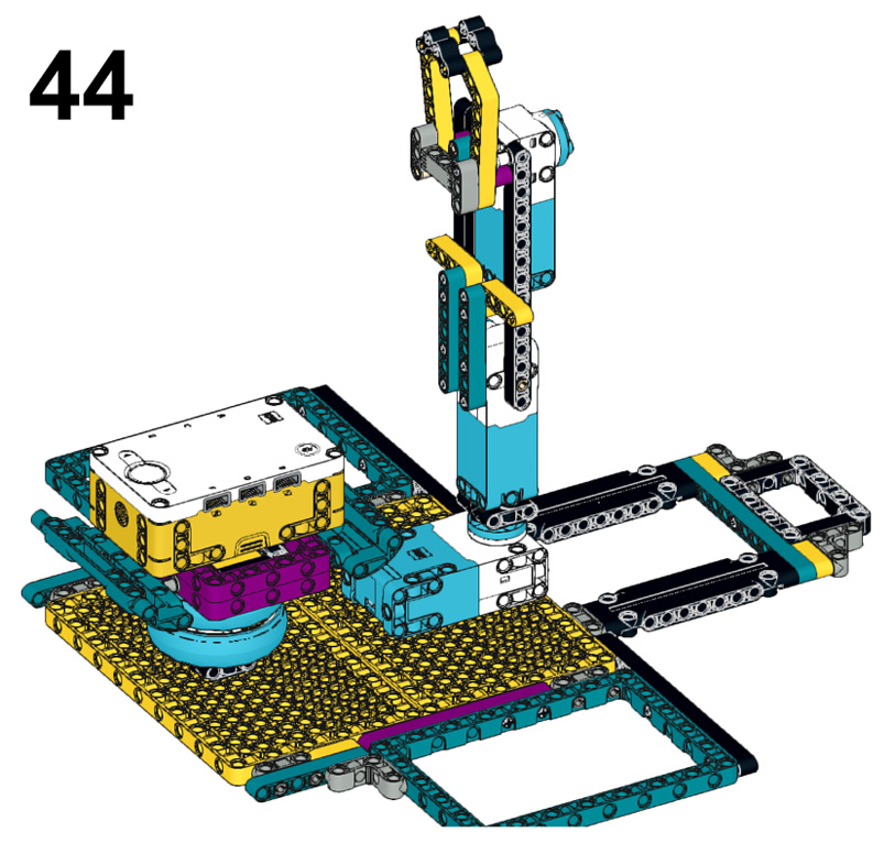
Figure 2.47 – Final view of the robot
Now that your claw is complete, we have one more item to build, which is an element to be picked up, so let's build a small cargo element.