Avionics systems and subsystems of drones
Post the mechanical system comes the avionics system, which is fitted into the mechanical system at appropriate required places to exert thrust and other forces, keeping the center of gravity balanced. These avionics systems include sensors and actuators powered by the power system to exert the necessary force where required and get the necessary task done by the drone:
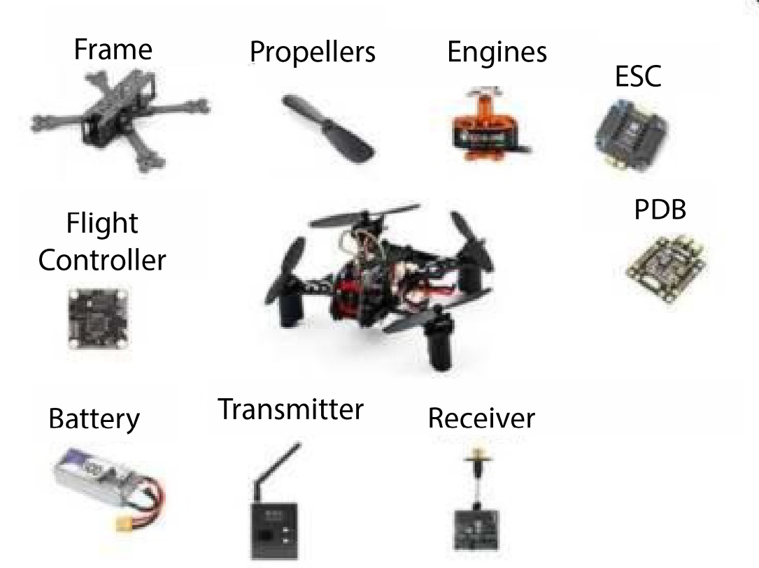
Figure 1.17 – Avionics components
In the following sections, we will have a glance at the major avionics systems and subsystems of a drone that are interrelated.
The propulsion system or drive train of a drone
The propulsion system is responsible for creating the necessary force to lift the system into the air, maintaining the ratios of lift to weight. This is also a reason to maintain stability in the air, fly at high altitudes, and provide speed to the system. This is the most important part and initial building block of drone systems. It also helps in maintaining electrical stability in the system:
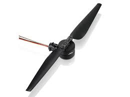
Figure 1.18 – A power train
It consists of the following primary parts:
- Motors: These are the primary components of the propulsion system. These are brushless DC (BLDC) motors, which are far more efficient and lower-power-consumption motors with a long life. These motors rotate at high speed with propellers and produce the necessary thrust to lift the system in the air. Most of the power of the battery is consumed by these motors. These motors are the primary actuators to create motion in the 3D space, travel from one position to another, and lift loads:
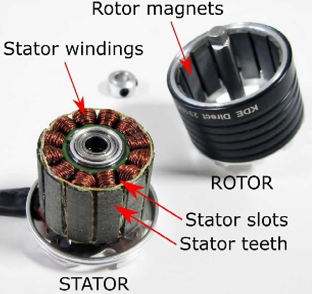
Figure 1.19 – A BLDC motor
- Propellers: Propellers are key thrust generators in the multirotor. These are mounted on the motors using screws or other mechanisms. Propellers are manufactured with lightweight materials in such a way that when rotated at high speed, they push the air downward, produce thrust, and lift the system upward. Each propeller produces a set amount of thrust when rotated at a desired RPM, which we will see in the coming chapters:
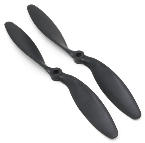
Figure 1.20 – Propellers
The power system of drones
The power system is the system that is responsible for powering the whole drone with its payload and other peripheral devices. This is the key system that keeps a drone powered, helps in getting the required endurance, and nullifies the effects of high wind or heavy maneuvers. Certain buck-and-boost converters and filters are added to step up and down voltages when required, and current consumption is greater.
These are the major components of the power system of drones:
- Battery: The battery is the most important part of the system. It serves as a key source of power delivery to the system. All systems and subsystems are powered by the battery. The battery must be capable of delivering power as required by the system without failure and serve the current delivery. It is also responsible for deciding the endurance of the drone:
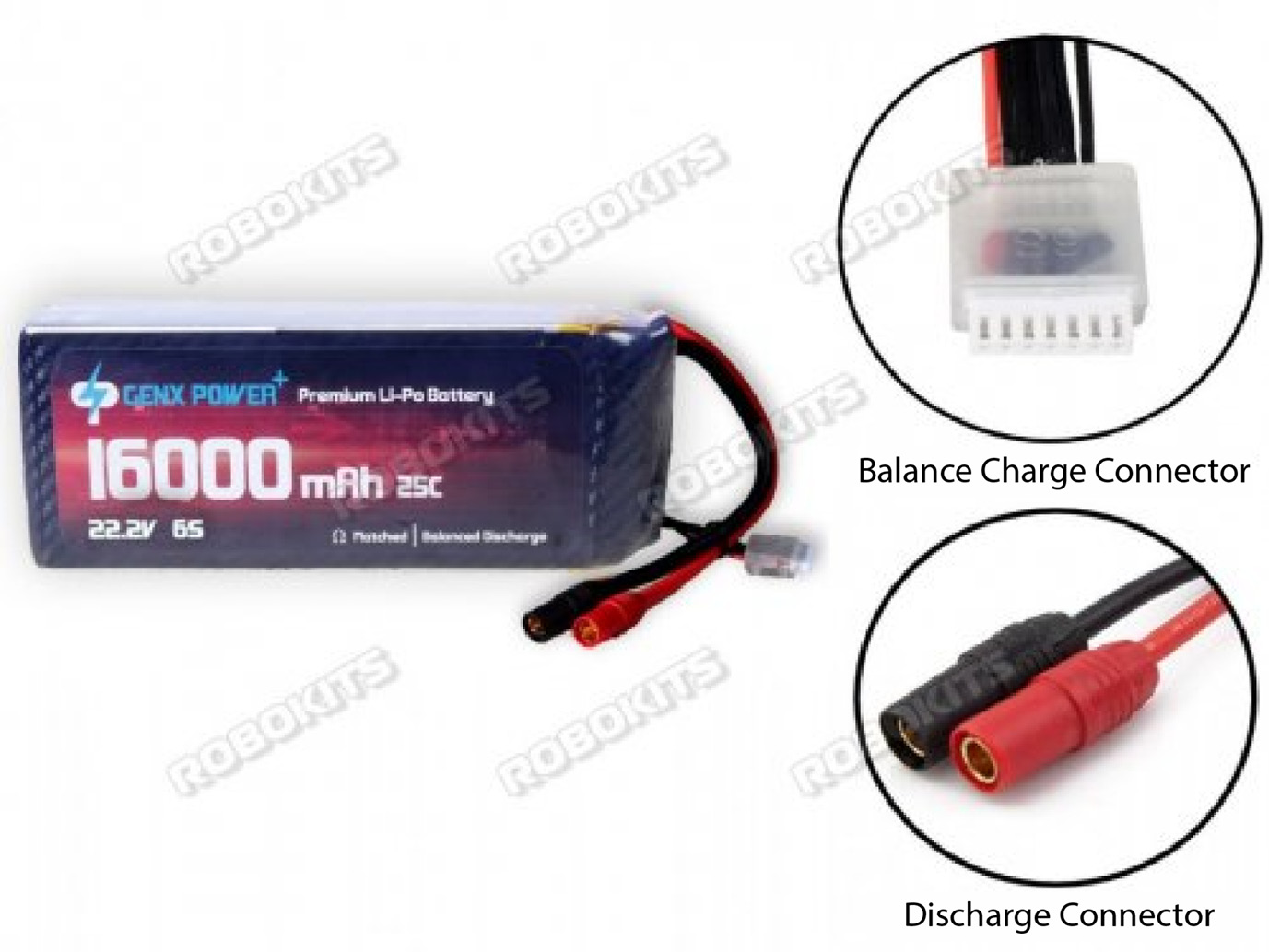
Figure 1.21 – A battery
- Power distribution board: The power distribution board, as the name suggests, helps to distribute power to different systems. High-power-consumption elements such as motors take power through this board, and it is evenly distributed among them. A few more filtering elements are added, such as a capacitor to prevent any part from burning due to surges and extra load current:
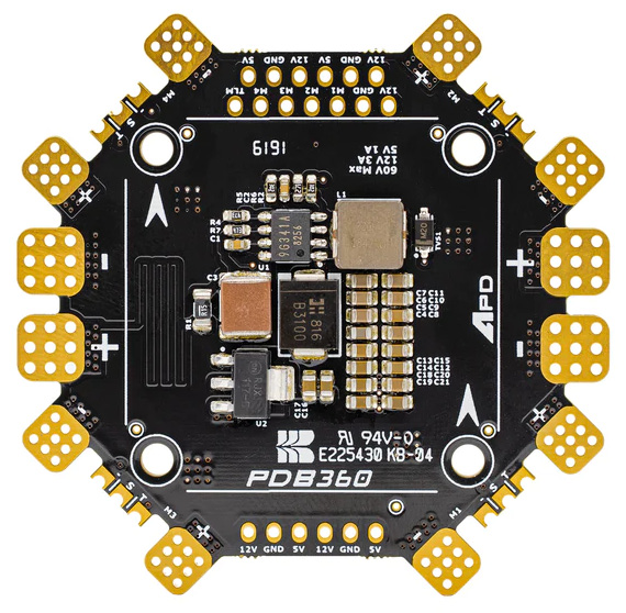
Figure 1.22 – A power distribution board
- Buck-and-boost converters: Buck-and-boost converters are used in the circuitry to step up or down the voltage as required by peripheral devices and satisfy the needs of current requirements. These are used as per the power specifications of the payload:
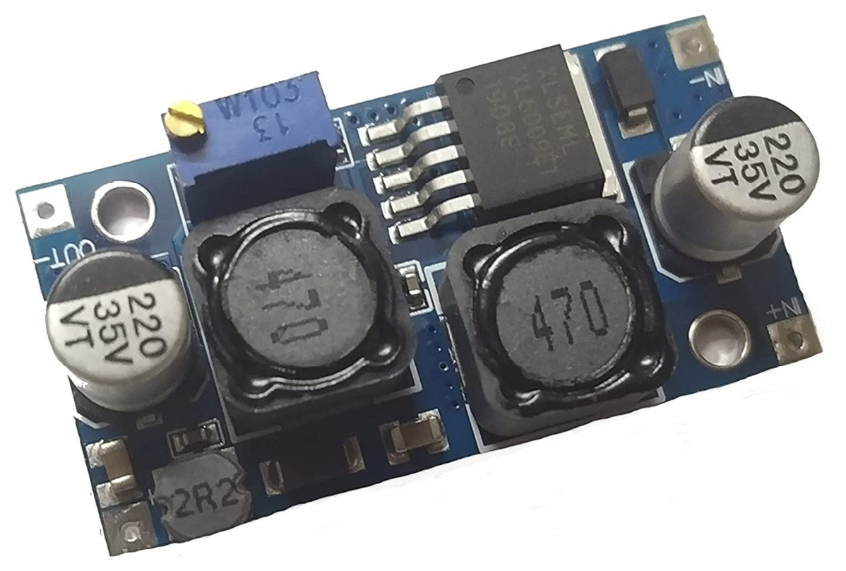
Figure 1.23 – A step-down converter
Command and control system
This is a system that helps connect a drone for command and control and helps to keep the drone in check and in control. It is only due to this system that drones remain in control and can be controlled and operated in the way the pilot wants. This system also helps to keep drone health in check and enables real-time monitoring of sensor data.
The major parts that together make a communication system are the following:
- Remote control (RC): An RC device, or remote controller, is used to fly the drone under the visual LOS (VLOS). It helps to manually fly the system to any place and any orientation. It helps to change the mode of flying and also take control of the system during autonomous missions.
However, it does not have live monitoring of the system’s sensor data and cannot see the live health of the system:
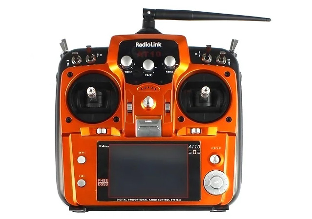
Figure 1.24 – An RC
- Ground control station (GCS): A GCS is an integrated control station that is used for system configuration and ground testing of systems, as well as to keep a check on system health and sensor data, and for command and control over drones for LOS and beyond VLOS (BVLOS) applications. A GCS is responsible for mission planning and execution in a completely autonomous mode. It is also responsible for the auto-tuning of systems for smoother flying:
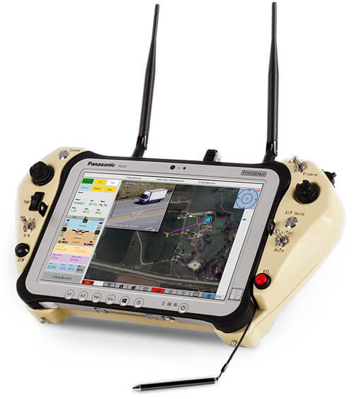
Figure 1.25 – A handheld GCS
- Radio modem: A radio modem is a prime device used to communicate between a GCS and a drone. The range of the system depends upon the range at which radio modems communicate. It helps as a key communication link to control and command drones from the GCS. The radio modem helps to provide security to the link and transmit signals on which the GCS and drones communicate:
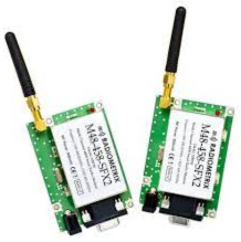
Figure 1.26 – A radio modem
- Antennas: Antennas play a key role in signal transmission and propagation. The antenna gains and orientation decide the range of the system and the degree to which it can move in the air. The type of antenna is an important parameter in deciding the range of a drone or bird, which we will see in later chapters:
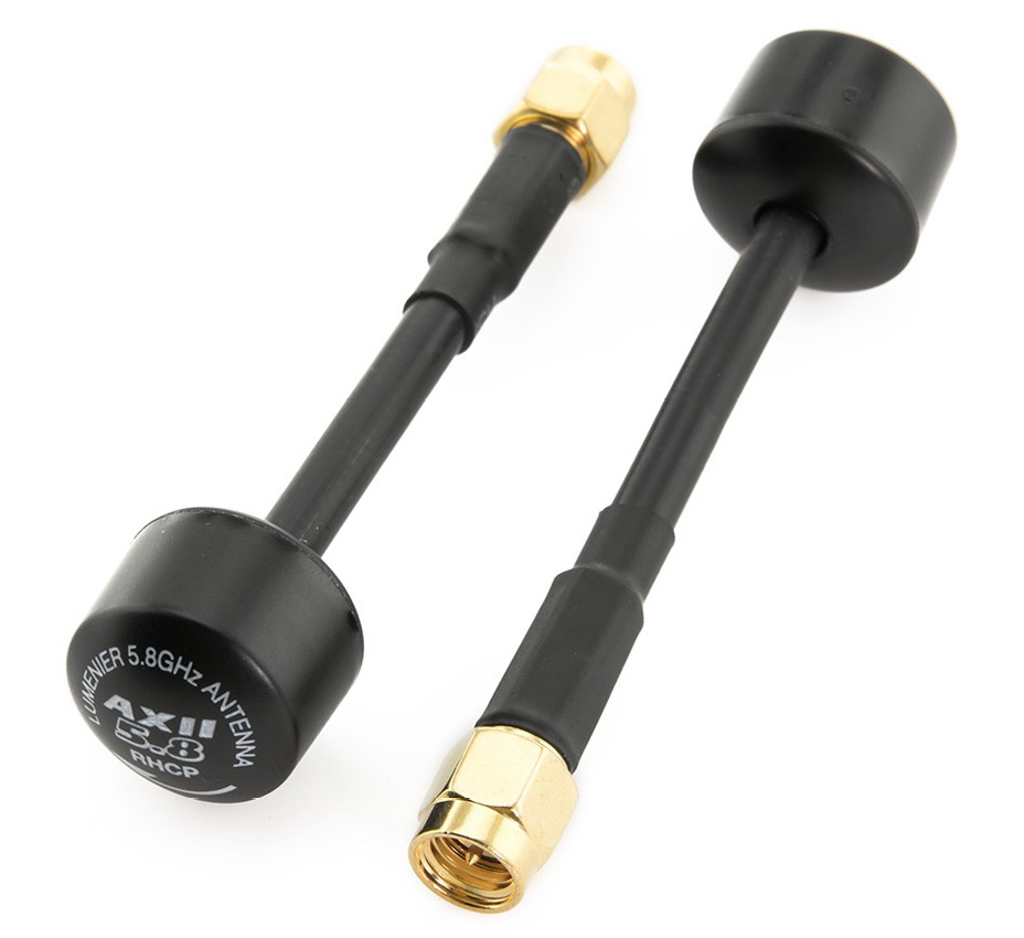
Figure 1.27 – An antenna
- Navigation system: Post power, propulsion, and communication comes the navigation system. This navigation system is only helpful when driving the system in autonomous mode. The navigation system helps the drone to decide the direction and coordinates and moves in a particular direction autonomously or as guided in the mission.
The drone is able to move in the selected paths and directions with the help of the navigation system, which is supported by built-in sensors. Major components that enable navigation systems are the following:
- GPS: The GPS is a key component of the navigation system. The GPS used in drones has a GNSS such as Galileo, BeiDou, and other similar navigation systems embedded in it, which helps in getting real-time coordinates of the drone to display in the GCS and helps the pilot in getting real-time maps and locations. The same GPS coordinates are used by mission-planning software to decide the autonomous path of the drone and by the drone to navigate to the provided GPS coordinates. The take-off coordinates are also saved into the drone, which helps the drone to do Return to Launch (RTL) while in failsafe conditions:
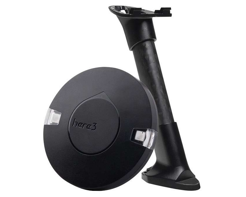
Figure 1.28 – A GPS
- Compass or magnetometer: A compass or magnetometer is a crucial component of the drone navigation system. A GPS gives you the coordinates of the system and the desired go-to location, but a compass gives you the direction in which the drone travels. Drones travel to particular coordinates with the guidance of a compass. The compass gives the heading of the drone where the nose of the drone travels. The compass needs to be calibrated with respect to the magnetic field of the space for proper navigation:
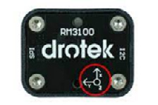
Figure 1.29 – A magnetometer
- Processing unit or flight controller: The flight controller is the central processing unit (CPU) of the drone. This is called the brain of the drone. The flight controller receives the sensor data from the inbuilt sensors and peripheral sensors and delivers it to the actuators and motors, thus making the drone fly in manual as well as auto mode.
The flight controller is programmed to behave in a particular manner in various flying modes and missions and under certain conditions, which we will see in the coming chapters:
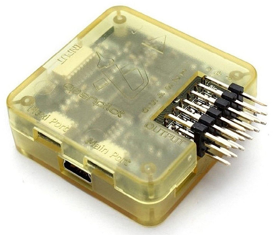
Figure 1.30 – A flight controller
- Payload: A flying machine is to be used for some application and work for which it is designed and developed. The device that executes that particular work while being on the drone is called a payload. For example, a day/night camera is a payload for day/night surveillance (see Figure 1.31), a spray tank is a payload for an agriculture spray drone (see Figure 1.32), and an RGB sensor is a payload for a survey drone.
The payload is the only object that does the job a drone is intended to do. We will see working with similar payloads later in this book for different applications:

Figure 1.31 – A camera payload
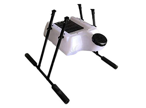
Figure 1.32 – A spray tank as a payload
These are some of the main components that are used in a drone system. In a later chapter, we will look at the specifications used for each of the components and how they can be best optimized to build a drone for a particular specification.


